Why you need complex numbers
2024-02-12 math electronics
I plan to use complex numbers in an upcoming article, and I thought I'd better post some introductory material about them first. Of course, there are many introductions to complex numbers on the Net already and there may not be much new I can say; so rather than focusing on what complex numbers are, which you can find almost anywhere, I thought I'd come in from a different direction and talk about why you should care about them.
As with any mysterious thing in science and technology, you can get a lot of benefit by asking the question, "What problem does this thing solve?" If you know what problem the thing solves, then you've got a good start on understanding how it works.
Circuit analysis breaks in AC
Complex numbers can solve a lot of different problems, but one you might care about is the problem of making basic circuit analysis work properly in AC circuits. That's also the problem I'll be looking at in my later articles supported by this one, so it's a good place to start.
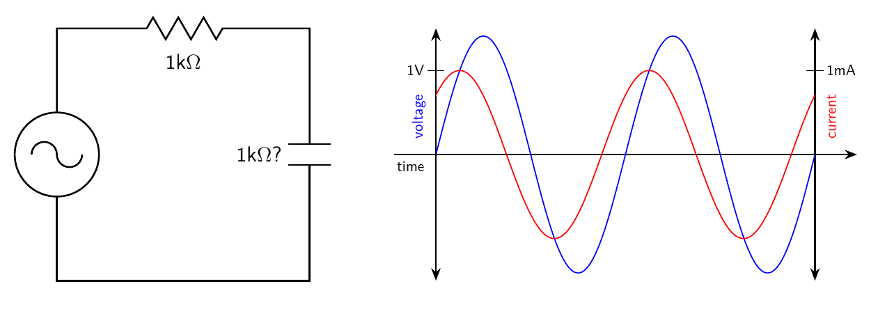
Maybe you've got a very simple AC circuit, just a sine-wave generator applying power to a theoretically ideal 1kΩ resistor. The voltage of this generator will be discussed in a moment; its frequency isn't important, but just assume it's running at some fixed frequency.
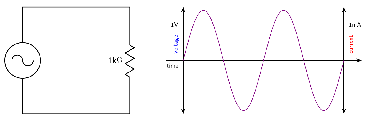
The current through and voltage across the resistor are plotted at right; formally, these are two curves on two separate scales, but the blue voltage curve and red current curve happen to coincide, so I've plotted just one purple curve. The ideal resistor obeys Ohm's Law: current at every moment is exactly proportional to voltage, in this case at a rate of 1mA per 1V (or 1000V per 1A); therefore the resistance of this resistor is 1kΩ.
What is the voltage here? The peak of each voltage wave is somewhere above 1V, and then there's an opposite peak in the other direction. In fact, I've drawn the diagram to make the peaks 1.414V high. As discussed in my earlier article on levels, when talking about AC it usually makes sense to talk about RMS voltage, which is the equivalent DC voltage that would dissipate the same power into a resistor. With a plain sine wave like this one, the RMS voltage is 0.707 times the one-sided peak voltage, which works out to 1V. This is actually a 1V sine wave. The sine-shaped current is, similarly, 1mA RMS. Even though it's AC, Ohm's Law applies perfectly: 1V equals 1kΩ times 1mA.
We know what happens when we put resistances in series. The result is equivalent to the sum of the two resistances. I've written another article going into more detail on combining components in series and parallel, and it's also possible to level up on that with additional rules that go beyond series and parallel. If we put two of our 1kΩ resistors in series, the voltage and current should be consistent with a total resistance of 2kΩ.
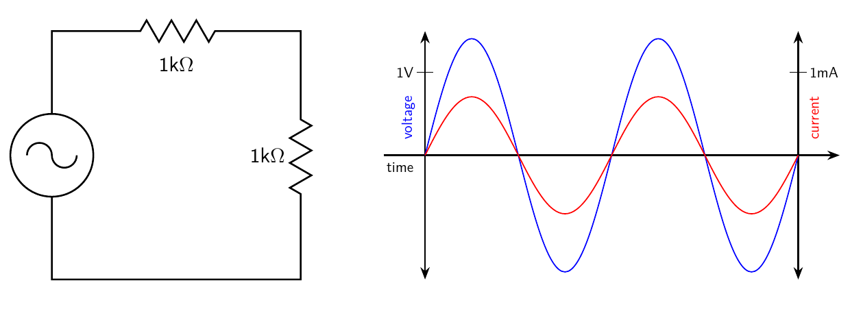
And that's what happens. With the voltage remaining at 1V RMS, the current drops to 0.5mA RMS, and the Ohm's Law calculation still works: 1V equals 0.5mA times 2kΩ.
Now suppose we want to play with a capacitance instead of a resistance. I'm saying "capacitance" rather than "capacitor" to emphasize that I'm talking about a theoretically ideal component. Let's say that this capacitance is chosen so that, at the fixed frequency of the generator, it passes basically the same current as the 1kΩ resistor earlier.
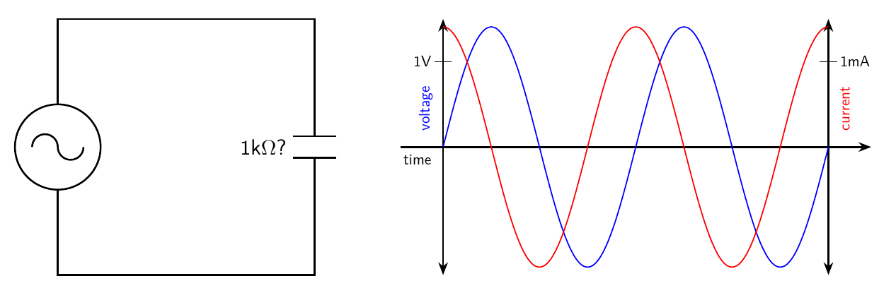
Just like with the single 1kΩ resistor, we have 1V RMS of voltage, and 1mA RMS of current. But something is different here: the curves don't line up anymore. The capacitance is sort of anticipating the generator, because the current curve always peaks 1/4 of a cycle before the voltage curve, just as the voltage curve is crossing zero.
That's not so mysterious if you think about what the capacitance actually does, in terms of storing charge. At and immediately after the zero-time mark, with the capacitance's charge level at 0V but about to increase, the generator has to push current into the capacitance in order to increase the voltage, at a rate determined by the slope of the voltage curve which happens to be maximized at the moment it crosses zero. As the voltage increases, the capacitance is more charged and the voltage is increasing less rapidly, so the current needed to make that change gets smaller. At the moment where the voltage goes flat and for a moment is neither increasing nor decreasing, that's when the generator no longer has to provide current to change the voltage. And then as the voltage decreases, the generator actually has to absorb current in the reverse direction to decrease the charge stored in the capacitance.
Those familiar with calculus will note that the current in this case is pretty much the same thing as the derivative of the voltage with respect to time.
But if we just look at the RMS values without thinking about it in calculus terms as a function over time, we can note that the numbers are just the same as with the 1kΩ resistor. We have 1V applied, we have 1mA of AC current flowing, and Ohm's Law still works fine, so the capacitance is equivalent to a resistance, or at least something that it's tempting to call a "resistance," of 1kΩ.
Because I'm hinting that it's not actually quite so simple, I have put a question mark next to the "resistance" on the diagram. This capacitance sure seems to be behaving like a 1kΩ resistor, but should we really believe that?
If we really believe that the capacitance is equivalent to a 1kΩ resistance, then we should be able to put it in series with another 1kΩ resistance, like for instance the original resistor, and get 2kΩ. Try doing that.
Things have gotten complicated here. The RMS voltage applied across the two components in series is 1V. By simple arithmetic, 1kΩ plus 1kΩ equals 2kΩ. Then the RMS current ought to be 0.5mA. But the RMS current is actually 0.707mA (note that equates to a peak current of 1mA), significantly more than it ought to be. Applying Ohm's Law, 1V divided by 0.707mA gives a "resistance" of only 1.414kΩ. We've just added 1+1=1.414 and lost several hundred ohms somewhere. Another hint at what's happening is in the timing of the current peaks: in the series circuit, current anticipates the voltage somewhat, but not as much as with the ideal capacitance alone. In fact, it's a matter of 1/8 of the generator's cycle. The current waveform here is a sort of compromise between what the resistor and capacitance each did by themselves.
It can actually get much worse than just 1+1=1.414. I omit the intermediate steps, but you could find an ideal inductance which, like my example capacitance, passes 1mA RMS when subjected to 1V RMS. Inductances have current that lags behind the voltage by 1/4 cycle, proportional to the integral instead of the derivative of voltage. If you put that "1kΩ?" inductance in series with the "1kΩ?" capacitance, everything blows up.
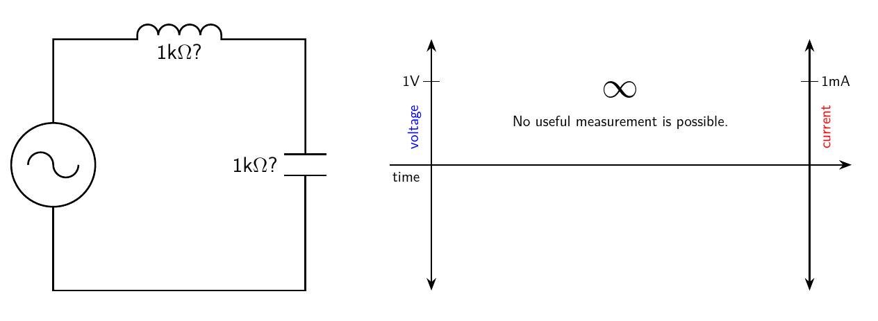
The current in this case, with ideal components, is theoretically infinite. If you try to build it with real (necessarily non-ideal) components, then the current will merely be very large, driving your generator to its limits and maybe overheating the components. No useful measurement is possible in such a situation. The combination of two components in series is like a short circuit, even though each one was reasonably well-behaved by itself. We appear to have added 1kΩ plus 1kΩ and gotten a total of zero resistance. Ordinary arithmetic has failed again.
And that is one of the problems complex numbers can solve in electronics: making sense of voltages, currents, and resistances in AC circuits, where ordinary arithmetic fails.
Reactance is sideways resistance
One way to try to make sense of the above would be to dig deeply into the underlying calculus. If instead of calling the voltage "1V AC" you actually write it down as an appropriately-scaled sine function, you can use the knowledge that capacitors pass current proportional to the derivative of voltage, and inductors pass current proportional to the integral of voltage, and write down expressions for current and the voltage to current ratio (which we'd like to call "resistance") and you can have all the math be valid and accurately describe what the circuits really do. But that's a huge mess. It would be nice to have a better, simpler way of understanding things with only algebra and not calculus.
One observation that seems quite suggestive is that 1.414 isn't just a random number; it's recognizable as the square root of two. It happens to be the hypoteneuse of a 45-45-90 triangle with the other two sides being of unit length.
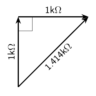
If you confuse ohms with meters, walk 1kΩ North, turn at right angles, and walk 1kΩ East, on a flat Earth, how far are you from your starting point? You're 1.414kΩ away, the same as the number that came up in the resistor-capacitance circuit earlier.
And that's not just a coincidence. If you do more experiments with resistors and capacitors of different sizes, it turns out that the overall apparent resistance (meaning the ratio of RMS voltage to RMS current) always ends up being the hypoteneuse of a right triangle where one side is the apparent resistance of the resistor and the other is the apparent resistance of the capacitor. It also works with inductor-resistor circuits, as long as you don't try to use inductors and capacitors in the same circuit. But if you do try to use inductors and capacitors in the same circuit, they don't "add" according to a right triangle; they just subtract, including in the extreme case of an inductor and capacitor with equal voltage-to-current ratio, which give a total of zero resistance and everything blows up.
What we're groping toward here is a geometric interpretation of how the components behave. Resistors have resistance and we think we understand that straightforwardly. The thing that capacitors have is sort of like resistance, but it is sideways. It behaves like resistance rotated 90°. The thing that inductors have is also sort of like resistance, but it is rotated 90° in the opposite direction from the thing that capacitors have. So when you add them up, resistors with either capacitors or inductors end up creating a right triangle, and capacitors and inductors with each other end up pulling in opposite directions.
Another intuition that supports the idea of using geometry is that when an AC circuit is operating at a fixed frequency, with all the voltages and currents cycling in a regular rhythm, that is very much like something rotating. If the AC is being generated by a rotating machine, then there may actually be a physical object that rotates in sync with the electrical waveform. So if we talk about the current being a little bit ahead of, or a little bit behind, the voltage - as actually happens with the current through a capacitor or inductor - the amount of lead or lag in time has a natural interpretation in terms of an angle. The capacitor's current anticipating the voltage by 1/4 of a cycle can also be said to anticipate the voltage by 90°, which is 1/4 of a circle, and the inductor's current can be said to lag voltage by 90°. The current in the resistor-capacitance example circuit anticipated the voltage by 1/8 of a cycle, naturally corresponding to a 45° angle.
Furthermore, the sine and cosine functions associated with AC come from trigonometry, where their inputs are the angles in triangles. It makes a lot of sense that the timing of waveforms in an AC circuit ought to be connected with angles and we ought to be able to draw all these angles as literal geometric angles.
It's cumbersome to keep saying "the thing that components have instead of resistance"; or to use terms like "apparent resistance"; and it's a problem to say "resistance" for something that really isn't, and then have people complain when the numbers don't add up; so it makes sense to introduce some new, standardized words for these concepts, as follows.
- What resistors have is resistance.
- The sideways thing like resistance, exhibited by both capacitors and inductors, we will call reactance.
- Capacitors have, more specifically, capacitive reactance, and inductors have inductive reactance.
- Capacitive and inductive reactance are really two aspects of the same phenomenon, going in opposite directions, so for math purposes we will adopt the convention that inductive reactance is positive and capacitive reactance is negative. Also, capacitive reactance is 90° clockwise from resistance and inductive reactance is 90° counterclockwise from resistance. (There are reasons for these choices which have to do with other sign conventions used in math, but for electronics purposes we can basically call the choice of signs arbitrary.)
- More complicated circuits and non-ideal components may often exhibit both resistance and reactance at the same time. We will use the term impedance for the more general concept that may include resistance, reactance, or a combination of the two.
- The variable name for resistance is traditionally R; for reactance, X, or more specifically capacitive reactance XC and inductive reactance XL; and for impedance, Z.
Thinking of components as having impedances, and impedances as representing movement from point to point in two dimensions (that is, vectors), makes some calculations easier, and more importantly, it makes those calculations produce correct answers. If you measure the voltages and currents through resistors, capacitors, and inductors individually, find the resulting resistances and reactances, then plot them carefully in the proper directions (resistance in one direction, capacitive reactance rotated 90° from that, inductive reactance rotated 90° the other way), then you can add them up and the result will correctly tell you what voltages and currents you can expect to see in series circuits, where the impedances ought to add.
But this geometric way of calculating is somewhat messy, and it still doesn't answer a lot of questions one might like to answer. For instance, if you build a voltage divider with generic impedances at the top and bottom, then to figure out what voltage comes out of the divider, you need a way to divide impedances instead of just adding them, and it's not at all obvious what's the right way to do that if they are just arrows drawn on the geometric plane. That problem follows from the more general difficulty with figuring out how to put two impedances in parallel when they are considered as vectors.
Turning arrows into upgraded numbers
At this point it's possible to view the problem more clearly: it's something to do with numbers. We want to express impedances using things of some sort, and we want those things to behave a lot like numbers so that we can add, subtract, multiply, and divide them. But it seems they can't be just ordinary numbers, because they need to be somewhat two-dimensional, expressing concepts like "rotate 90°."
With ordinary real numbers, you can take a number x and multiply it by 1, and the result is just x again. Call that a zero-degree rotation. You can multiply x by -1, and you get -x; that is, x in the opposite direction. That's a 180° rotation. Just using real numbers, with negative numberss to express the concept of "going in the opposite direction," seems to work fine as long as the only directions we care about at 0° and 180°. What's making trouble is the idea of rotating by other amounts, in particular 90°.
Well, just suppose we had already solved that problem. Suppose that a magic number dropped out of the sky that would have the effect of a 90° rotation counterclockwise, just like 1 gives a 0° rotation and -1 gives a 180° rotation.
In electrical engineering this number is traditionally called j.
Let's write down how this number might be used:
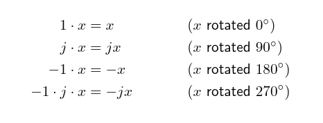
The last line shows stacking up two rotations: to get 270° of rotation, which is the same as 90° in the opposite direction (thus, clockwise), we can just multiply by both j and -1.
If this is going to work, then it also ought to be possible to stack up two 90° rotations and get 180°. So multiplying by j twice ought to have the same effect as multiplying by -1. Applying a little more algebra, all on the assumption that this is going to actually work, gives a big clue to what this mysterious j really is.
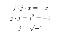
Traditionally, you're not allowed to take the square root of a negative number. If you multiply any real number by itself, you always get a non-negative number: positive times positive is positive, zero times zero is zero, and negative times negative is positive. So the answer to "What number did we multiply by itself to get a negative number" seems like it has to be "there is no such number."
But we can play the "What if?" game here. We can say, okay, suppose there was a number that happened to be the square root of -1? And it turns out that if we make that assumption, we don't need to break any other rules. All the rest of arithmetic still works if we just assume that there is a number j with this property.
If we're playing the game of "arithmetic with j allowed," then in general we're going to be working with combinations of ordinary real numbers like 1.23, and real numbers multiplied by j, like 4.5j. A single "number" might be a combination of both, like "1.23+4.5j." But it can't get any more complicated than that, for instance with higher powers of j that can't be simplified away, because we can always apply j2=-1 and similar rules to reduce a more complicated expression.
In mathematics, this system is called the algebra of complex numbers. The ordinary kind of numbers not involving j are called real numbers, as usual. Multiples of j are called imaginary numbers; and in most mathematical fields the square root of -1 is referred to as i. I'm using j here as that is the tradition in electrical engineering. When you have a fully general number that might contain either or both of real and imaginary components, it's called a complex number. Real, imaginary, and complex numbers correspond to resistance, reactance, and impedance respectively.
The real and imaginary parts of a complex number can be used quite naturally as the x and y coordinates for plotting the numbers on a two-dimensional plane.
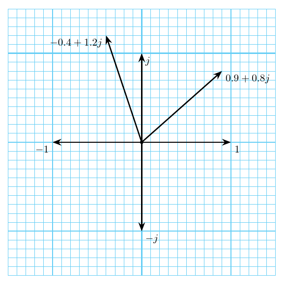
An arbitrary complex number might be represented by the variable z and written as z = a + bj; then a is the real part and b is the imaginary part. By applying a little algebra and using the rule j2=-1, we can derive formulas for adding, subtracting, multiplying, and dividing complex numbers in this form. All of them are pretty straightforward except division.
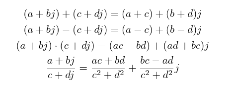
As a sanity check, try substituting b=0, d=0 into those formulas and simplifying them. That shows how they apply to pure real numbers with no imaginary components; and the result is just ordinary addition, subtraction, multiplication, and division on real numbers.
All the familiar rules of DC circuit analysis still work in an AC context if we just allow voltages, currents, and impedances to be complex numbers and use the rules of complex arithmetic shown above.
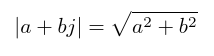
One missing piece is that we need a concept of "absolute value" that works on complex numbers. I'll say without proof that the following formula works; and as with the others, you can sanity-check it by calculating what it does to a pure real number with zero imaginary part. You can also note that it's just the Pythagorean Theorem formula for an hypoteneuse, expressing the geometric idea that the real and imaginary parts are at right angles to each other.
Now, as an example, here is the calculation for what's going on in the resistor-capacitance example circuit from before, using complex numbers.
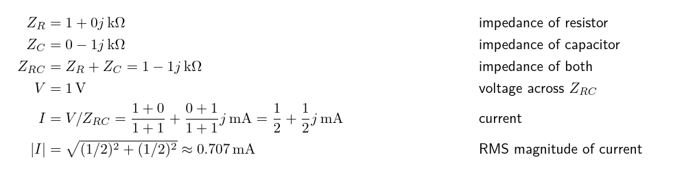
That gives the correct answer without ever needing to assert that 1+1=1.414. Moreover, and this is an important advantage over the pure geometric vector-addition approach, we can do a similar calculation for a parallel circuit, using the standard formula for parallel resistances applied to complex impedances, and that gives the right answer too.
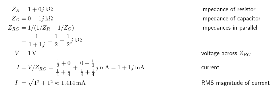
In that particular example it might be even easier to compute the complex currents for the resistor and capacitor separately and then add them; but computing an equivalent single impedance for the combination would become necessary in some more complicated circuits, so it's worth demonstrating that doing it does work.
I've barely scratched the surface here of the ways complex numbers can be used in electronics. In particular, I haven't discussed how to compute the reactance of a capacitor or inductor in ohms, based on the frequency and its capacitance or inductance in the more familiar units of farads and henries. Some of that stuff will be in the future articles I wrote this one to support. Complex numbers also have many other uses in mathematics in general beyond electronics, the Mandelbrot set being a spectacular example. I wrote about Mandelbrot set music in 2017 and again in 2020.
Appendix: bonus material
For people who already knew about complex numbers and have slogged through this discussion nonetheless, here are a few extra bonus items. Feel free to skip them if this is your first encounter with complex numbers.
More terms for circuit-related quantities
Above I talked about resistance, reactance, and impedance, all measured in ohms. But each of these has an inverse (reciprocal) quantity measured in siemens (or, archaicly, "mhos"), and there are words and variable names for each of them.
- The inverse of resistance denoted by R is called conductance, denoted by G.
- The inverse of reactance denoted by X is called susceptance, denoted by B.
- The inverse of impedance denoted by Z is called admittance, denoted by Y.
Between resistance and conductance, or impedance and admittance, the "inverse" relationship is just the reciprocal: R=1/G, G=1/R, Z=1/Y, Y=1/Z. In the case of impedance with both real and imaginary parts, you have to do a proper complex division, not just take the reciprocals of the parts separately. That is also why there's an extra negative sign in the relationship between reactance and susceptance: a pure reactance of X actually means the impedance is jX, and then 1/jX is not j(1/X) but -j(1/X).
Who invented complex numbers?
Complex numbers appear to be part of the universe, deeply embedded in physics, so it may be more appropriate to describe them as discovered rather than invented. It also seems to have been a group effort. Italian mathematicians in the 16th Century were using the concept of the square root of a negative number, usually in an unsystematic way, as part of their efforts to solve polynomial equations. Rafael Bombelli is credited with being the first to introduce a specific, distinct notation for imaginary numbers, in a book published in 1572. Gerolamo Cardano wrote about imaginary numbers earlier, in 1545, and he is often credited with their discovery, but he did not have a clear understanding of their properties, and others earlier still also seem to have been using them in an indirect and confused way.

Are there further levels beyond complex numbers?
If ordinary real numbers can be upgraded, or "evolved" like pokemon, to become complex numbers with two components, is it possible to go further?
The answer is yes. Vectors with any number of dimensions are familiar, of course, but complex numbers are not exactly just two-dimensional vectors, so the interesting question is, are there further levels that go beyond complex numbers in something like the same way that complex numbers go beyond reals?
The next level up are the so-called quaternions, which are based on the idea of three distinct square roots of -1 which multiply in a non-commutative way (meaning that in general, a times b isn't the same as b times a when they are quaternions):
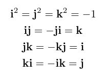
Whereas complex numbers can be thought of as describing rotation in two dimensions, quaternions describe rotation in three dimensions. The quaternions themselves have four dimensions: to write one down, you need to specify the real part and a value for each of the three imaginary parts corresponding to the three different square roots of -1.
Quaternions were discovered by William Rowan Hamilton in 1843, and there's an amusing story about his carving the defining equation on Brougham Bridge. He tried hard for the rest of his life to popularize them, especially in physics, and others in Scotland did the same for much of the rest of the 19th Century partly as a matter of national pride, but quaternions were mostly crowded out by vectors (and matrices and tensors) in the 20th Century. Nowadays, quaternions see some use in graphics programming and applications like aircraft and spacecraft attitude control, because they can be used to avoid "gimbal lock" when calculating rotations.
There is a thing called the Cayley-Dickson construction which can be applied any number of times to get an unlimited number of new systems of "numbers" (that is, algebras), doubling the number of dimensions at each step. From reals this construction generates complex numbers, then quaternions, and the next steps are "octonions" with eight dimensions and "sedenions" with 16 dimensions. However, you lose something at each level from 2 to 16 dimensions: quaternions are non-commutative, octonions are non-associative, and sedenions are non-alternative (which means they don't have even a weaker version of associativity that octonions still have). As a result, the levels past complex numbers no longer behave so much like things we can think of as "numbers." They're more abstract algebraic things.
From an algebraic perspective it might be said the complex numbers are the best numbers. You can factor every polynomial in complex numbers down to linear terms, which is often impossible with reals; and unlike the further levels in the Cayley-Dickson construction, you don't lose nice properties that numbers ought to have, such as commutative multiplication.
As well as those generated by the iterated Cayley-Dickson construction, there are also other kinds of "hypercomplex numbers" which were mostly cooked up and studied in the 19th Century and no longer well-known. These may be of interest to algebraists but they don't have the compelling physics connection that complex numbers and possibly quaternions seem to have.
Why is the letter j used for the square root of -1?
In electronics this is done because i might be confused with I for current. Other mathematical fields use i for "imaginary." But then the really interesting question is, why is I current in electronics?
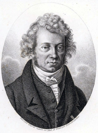
Apparently that was a decision made by André-Marie Ampère, who used I to stand for "intensité du courant" ("intensity of current") in 1820. The standard unit for measuring intensity-of-current, the "ampere" usually abbreviated to "amp," is named after him. English-language publications adopted this variable name later in the 19th Century; prior to that, they had used C for "current," which nowadays would conflict with C for capacitance.
◀ PREV Build your own commercial module part 4: manufacturing || Smith chart by projection NEXT ▶