Combining components for new values
2018-09-19 electronics design
When I started breadboarding the Coiler VCF, I ran into a problem: the design called for a couple of 6800pF (also known as 6.8nF) capacitors, and I didn't have any of those on hand. I didn't want to rush out and buy some, both because of the time and effort involved and because it was quite possible that design changes would mean I might not end up using that value in the finished product anyway. I could either end up paying a high price for a small quantity, or buying in bulk to get a lower per-unit price and having the extras go to waste. As I've written before, it's not a bargain if you end up paying for components you don't use.
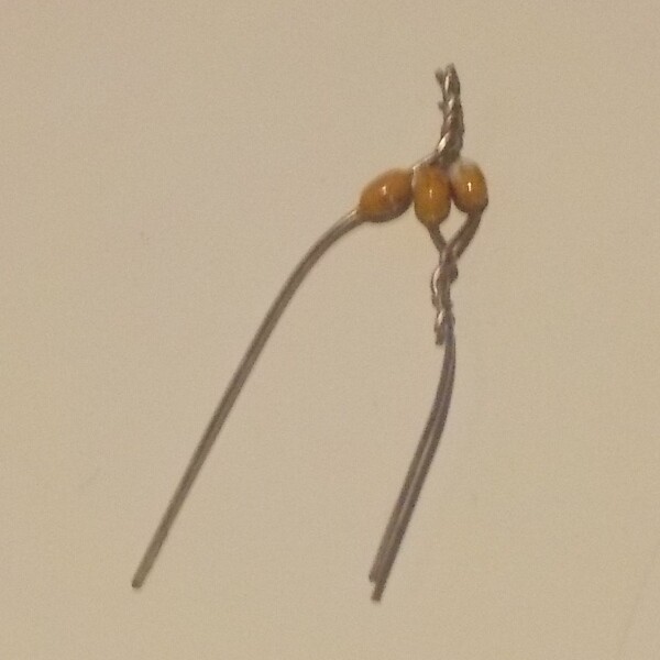
I had plenty of 10nF (also known as 0.01µF) capacitors in stock. So I put two of those in parallel, and a third in series with the pair of them, soldered the mess together, and the result had an overall capacitance of 6.667nF, close enough to the target to be usable for my testing purposes.
Knowing the rules for determining the equivalent value of a combination of components is useful both for situations like this, where you're trying to make up a given value you don't have out of components you do, and in the other direction, for understanding what's going on in a given circuit. In this posting I'll cover how these calculations work.
Series and parallel resistors
Resistors in series add their values, in a way that looks easy.
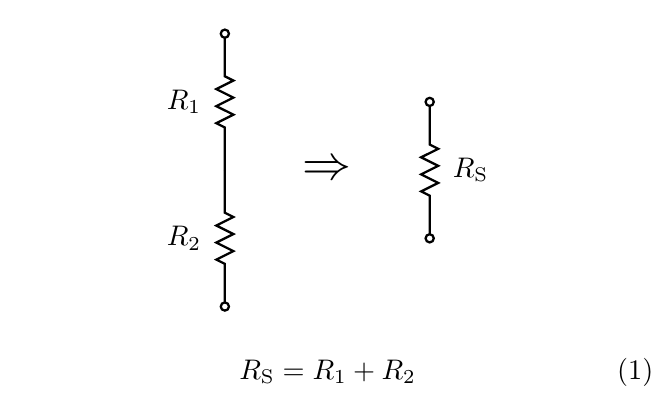
This formula is easy to derive from more basic rules. Current flows into one end of the pair, out the other, and there is nowhere else for it to come or go. So the current is necessarily equal in the two resistors; all current that flows through one necessarily flows through the other. Then each resistor has its own voltage drop determined by Ohm's Law, the voltage drop across the pair of resistors is the sum of the two per-resistor voltage drops, and then applying Ohm's Law again to determine the overall resistance gives (1).
There's also a way to calculate an equivalent value for resistors in parallel, but it's a little more complicated.
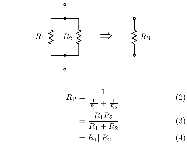
The formula (2) is how I prefer to do this calculation, not least because it is easy to generalize to more than two resistors in parallel. This formula, like the series formula, can be proven by applying basic principles: the two resistors have the same voltage across them, then Ohm's Law gives the currents through each; current through the pair is the sum of the per-resistor currents; and then Ohm's Law again gives the overall resistance (2), which is just the calculation I described with the common factor of voltage cancelled out.
Some people write and memorize (3) as the parallel resistance formula instead. That one comes from multiplying the top and bottom of (2) by R1R2 and cancelling, and the result is a formula that comes closer to meeting the usual customs of simplifying formulas in algebra. In some computational contexts it may possibly have numerical accuracy advantages. That formula is harder to generalize, though, and it's harder to look at it and see the direct connection to the underlying rules of voltage and current.
You will sometimes also see people write the symbol "||" (two vertical lines) as in (4). This symbol is not really a formula for parallel resistance, but it's a way of expressing the concept when doing calculations. The symbol "||", read "parallel," can be used as a binary operator like "+" or "×", and it has many of the same algebraic properties.
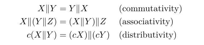
These rules can be used to simplify equations when analysing circuits with parallel components, in a way that would be harder without using a special symbol to represent what happens with resistances in parallel. Writing out (2) or (3) in full everywhere they are used inside a larger calculation, and needing to deal with algebraic simplification inside these formulas, is error-prone and messy.
But why is parallel connection complicated like this? Isn't there some easier way to think about it under which the case of resistors in parallel wouldn't need to use this concept?
In fact, there is. We traditionally think of resistors in terms of resistance, which is just their characteristic ratio of voltage to current. Ohms are defined as volts per ampere. Highly conductive substances like copper have low resistance for a given size and shape and not-very-conductive substances like most plastics have high resistance.
What if we flipped the definition around? Saying that a resistor requires one volt of drop for every milliamp it passes, is the same as saying it passes one milliamp for every volt. If we divide volts by amps we get ohms (1000 ohms in this case), but we could divide amps by volts instead. Such a ratio, the inverse of resistance, is called the conductance of the resistor (or other circuit element). Objects made of substances like copper have high conductance for their size and shape; those made of most plastics have low conductance.
Conductance is measured in units called "siemens": abbreviated S; often represented by the variable G; named after Ernst Werner von Siemens, who did early work on electricity; and note that "siemens" retains its final "s" even when used as a singular. One siemens is one ampere per volt, the multiplicative inverse of one ohm. Before the name "siemens" and symbol S were standardized for this unit, it was often called the "mho" ("ohm" spelled backward) and denoted by an Ω symbol turned upside-down. Whereas the ohm is a small unit and you usually have many of them, the siemens is a large unit and you usually have a small fraction of one. A resistor with a resistance of one kiloohm will have a conductance of one millisiemens. And the thing about conductance is that it adds in parallel, and does the same thing in series that resistance would do in parallel.
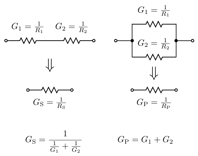
There's a nice duality among series, parallel, resistance, and conductance. Given a true statement about a circuit, we can swap resistances with conductances, and series connections with parallel connections, and end up with something else that's also true. Series connection of resistors seems easier than parallel just because we usually think of resistance rather than conductance; but it would make perfect sense, if confronted by a problem involving many parallel connections and few series, to switch our thinking to be in terms of conductance and understand the problem that way.
Inductors and capacitors
Inductors, or more properly inductances, follow the same rules as resistances.
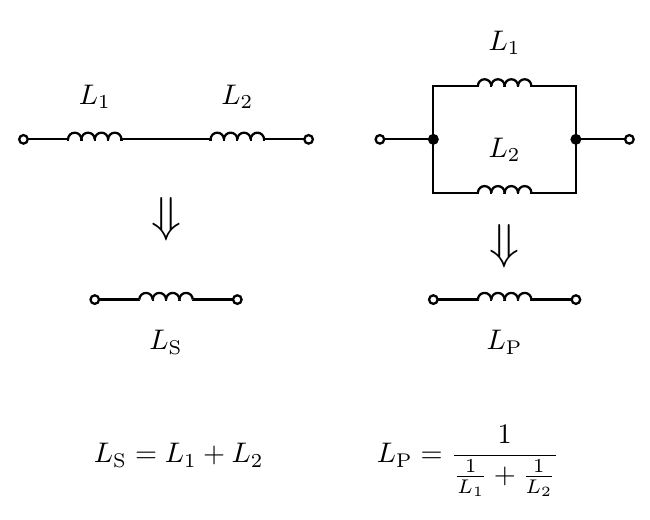
I drew a distinction between inductors (components) and inductances (the mathematical abstraction) in order to highlight non-ideal behaviour. These math rules apply to the abstract concept represented by an inductor: the behaviour of a component whose current is the time integral of its voltage drop. Real-life inductors often only approximate their ideal behaviour. The same is true of all other components too, but it seems especially likely to be an issue for inductors. They may actually function as if they had some built-in resistance and capacitance along with the inductance. There is also the issue that two inductors in close physical proximity may end up coupling through their magnetic fields, which can have complicated effects not expressed in these formulas. That being the case, you can't always just put two 1mH inductors in series and get exactly the behaviour you'd want from one 2mH inductor. But from the point of view of the mathematical abstractions, it is perfectly true that the same rules apply to series and parallel inductances that would apply to resistances.
What about capacitors? It's a fairly common beginner mistake to try to add up capacitances in series as we might do with resistances or inductances, but the correct rules are different.
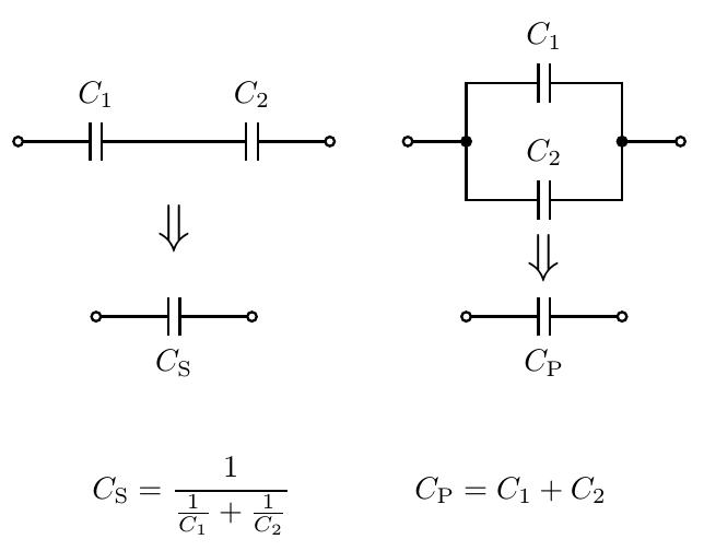
After the discussion of conductance it should be clear where these formulas came from. Inductance is a lot like resistance and so inductors add in series and use the inverse-of-sum-of-inverses formula like resistors. But capacitance is really more like conductance than like resistance. A high capacitance has more tendency to allow stuff through than a low capacitance. Smaller and smaller capacitances have less and less tendency to allow stuff through. So it makes some sense for the formulas to reflect that: series capacitances reduce the overall capacitance, and parallel capacitances increase it.
Here's an intuition for what's going on. Think about the tiny stray inductances and capacitances that arise when we build circuits. Anywhere you have a piece of wire you have at least a little bit of stray inductance. If you make the wire longer, the inductance gets greater. That is like putting many small inductances (of small sections of the wire) in series. It wouldn't make sense for a much longer wire to have less stray inductance; we would be constantly trying to splice in extra-long wires to make our circuits behave better, and it's obvious in practice that that isn't a helpful thing to do.
Anywhere you have two things near each other with an insulating medium between, you have at least a little bit of stray capacitance, which causes them to interact and can be a big problem for some circuits. Because the capacitances are small, this interaction mostly only happens at the highest signal frequencies. If you move the things with stray capacitance further apart, which is like putting more of these small capacitances in series, you get less interaction and less stray capacitance. If capacitances increased in series, then extremely distant objects would have basically infinite stray capacitance between them, allowing interaction at basically all frequencies. Components in our circuits on Earth would be constantly connected to circuits built by little green hobbyists in the distant Borgon Galaxy, and not strongly connected to other components on the same breadboard. Such a hypothetical is clearly is not how things work in real life; so it must be that capacitances decrease in series.
Circuit synthesis
The series and parallel rules are often useful but they don't really solve the original problem from the start of this article. I didn't start with three capacitors connected together and want to know their overall capacitance. Instead, I wanted to go in the other direction. I had a desired target and some limitations on the values of capacitors I could use without buying more, and I wanted to design a circuit to hit the target value as nearly as possible while using only components I had.
In all but the simplest cases, this kind of circuit synthesis problem requires some sort of trial and error. You go through different circuit topologies, guess values for some components, maybe apply algebra to calculate the values that would be needed for others to make the overall result work out, and then see whether those calculated values come close enough to matching the available choices.
I've created an online calculator to help with such questions. You can enter a target value for resistance, capacitance, or inductance, and choose a preferred value series (see my earlier Web log entry on preferred values) to help limit the components to values you may be likely to have on hand. Press the button, and it will come up with some options for hitting the target value as nearly as possible with up to three components from the chosen set of standard values. If you choose capacitors, "E1" (which means just the power-of-ten values), and "6.8nF", this calculator correctly finds the circuit that I ended up using in my breadboard, with three 10nF capacitors combined to make 6.67nF. If you play with it a bit, you may notice that it's usually possible to get very close to any target even with quite limited standard value series like E3 or E6. Once there are three components in the subcircuit the number of possibilities is so large that good approximations are relatively easy.
I've described how to convert networks of resistances into their equivalent values by applying series-parallel rules, and this is a very powerful technique. It's natural to ask, then, whether it is universal: is it always possible to calculate the resistance of a two-terminal network of resistors by applying these rules? The answer is no; there are networks which cannot be simplified by the series-parallel rules, and you might find it interesting to try to think of one. In some future Web log article I'll probably talk about those networks and how to handle them.
◀ PREV Common parts to keep in stock || Level up on circuit simplification NEXT ▶