One minute op amp analysis
2018-03-11 electronics design
You can understand most op amp circuits with just three simple rules.
- If, through negative feedback, the op amp can bring its inputs to equal voltage, then it will do so.
- Otherwise, it will drive its output near whichever power supply voltage corresponds to its more positive input.
- There is almost no current through the inputs.
There are circuits - especially those involving high speeds, reactive loads, or active components like transistors inside the feedback loop - where it's necessary to consider other issues as well; but the basic operation of nearly all op amp circuits can be understood with just these three rules. That's op amp analysis in one minute. Now, some examples.
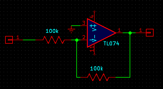
The basic buffer
Here's a common op amp circuit. How will it behave?

The input to the overall circuit is whatever it is, and goes into the positive input which detects its voltage. The op amp has negative feedback (through a connection between the output and negative input), so if it can, it will drive its negative input to the same voltage as the positive input. But the negative input is directly connected to, and thus at the same voltage as, the output. So the output will also be driven to an equal voltage to the positive input. The output voltage is the same as the input voltage.
Why use this circuit if the output is just the same as the input? Why not just use a wire? The answer is embedded in Rule 3: almost no current through the inputs. This circuit's input places almost no load on whatever's driving it; but it is capable of producing significant current on its output. For this reason it's called a buffer; it can be used between parts of a system to protect, or buffer, the source of a signal from effects caused by the load at the destination.
Although this circuit just as I've drawn it is very common in practice, there are a couple of caveats associated with it that mean it can't be used exactly as shown in every application. First of all, some operational amplifiers, including the very common TL074 shown (and JFET-input amplifiers like it, in general) have limitations on the input voltages they can accept. The TL074 data sheet specifies that inputs should be at least 4V above the negative power supply, which would be a limit of -8V in a typical Eurorack situation. If this rule is broken, then the op amp may exhibit a phenomenon called phase inversion whereby its output suddenly jumps to the opposite power voltage. For this reason, someone who wants to buffer a signal with a wide voltage range may actually be better off inverting it, with the circuit of the next section, or else carefully choosing a different op amp chip that can handle the desired input range. The inversion can usually be conveniently undone in some later stage of processing.
A less common restriction of some op amps is that the inputs must not be driven more than 0.6V apart - which is no problem as long as we are relying on Rule 1 and the op amp can keep its inputs at exactly the same voltage, but it becomes a problem in circuits designed to operate all or part of the time under Rule 2.
Another issue is that rule 3 says almost no current through the inputs. There is always a tiny DC bias current that flows through the inputs. It is quite small for the TL074, somewhat larger for some other types of op amps, and impressively minuscule in the case of a few expensive specialty chips. If there is nowhere for the bias current to go, it can cause problems. In particular, suppose someone wanted to build an AC-coupled buffer with a capacitor to block the DC:
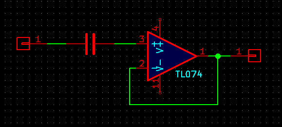
That capacitor will eventually charge up and throw the output voltage way off. It's necessary to add a high-valued resistor or similar to provide a path for the bias current:
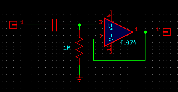
That circuit is really an RC high-pass filter concatenated with the original DC-coupled buffer.
Inverting amplifiers
Here's another common circuit frequently seen in synthesizer modules:
The two resistors form a voltage divider, probably best understood as an averaging circuit. The voltage at their centre connection is exactly the midpoint of the two voltages put into the resistor network, which are the op amp output and the circuit input. That is the op amp negative input, and it must be equal to the zero voltage at the other op amp input by rule 1. So what happens?
For any voltage applied to the circuit input, the op amp must drive its output to the opposite of that voltage in order for their average to be zero. This is a voltage inverter. Put in +1V, get out -1V. Put in -3V, get out +3V.
By changing the values of the resistors, it's possible to build inverting amplifiers that increase or decrease the magnitude of the voltages. For example, this one inverts and doubles its input voltage:
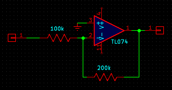
The negative input of the op amp in this circuit is called a virtual ground because, although it is not connected to the 0V or "ground" point of the system, it is driven to that same voltage by the feedback arrangement. Knowing that this point is always at 0V in normal operation can be useful in calculating currents into the circuit from other parts of a larger system.
Using such high-valued resistors as shown here (in particular, 100kΩ from the circuit input) is commonly done at the inputs of synth modules in order to keep the input impedance high; but it may not be ideal because such high-valued resistors can be associated with increased thermal noise levels. Circuits designed for high-quality low-noise audio tend to use lower component values and are designed around accommodating lower input impedances.
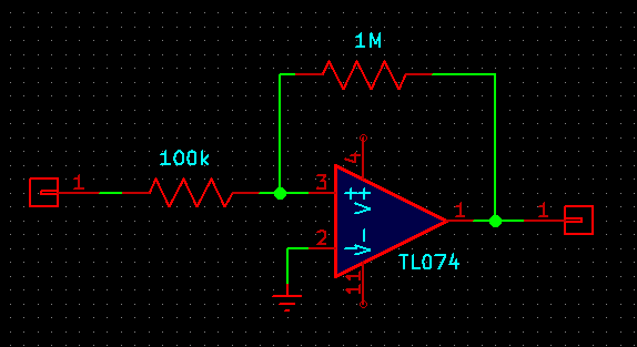
Non-inverting amplifiers
Remembering that the op amp inputs should be equal-voltage makes it easy to analyze non-inverting amplifier circuits, too.

Here the two resistors are in a 3:1 voltage divider arrangement. The negative input is 1/3 of the output, which means the output is 3 times the negative input, and since the two inputs are equal, it is also 3 times the positive input, as long as that remains possible within the power supply voltages. If it is not possible to amplify the circuit input by a factor of 3, (for instance, with inputs outside ±4V on a 12V power supply) then the op amp will just drive its output to the nearest power supply voltage, causing clipping.
But note that there is no virtual ground here. Since the circuit input goes directly to an op amp input, sufficiently wide-ranging input to this circuit (for example, driving the input all the way to the negative supply) could implicate the op amp chip's limitations regarding input range and cause phase inversion. When using this kind of circuit in a system, it's necessary to make sure either that it's used where such voltages won't occur, or that the chip can handle them.
A trickier circuit
Try this one.
At first glance it looks like the inverting amplifier circuit, with a gain of -10 because of the 10:1 resistance ratio. But look a little closer. The voltage divider is connected to the positive input; it is not an inverting amplifier. This type of circuit is called a Schmitt trigger (after Otto Schmitt, credited for inventing it) and it exhibits a useful effect called hysteresis. It's probably best understood as being similar to a typical thermostat.
If the thermostat for your furnace is set to 20°, then when the furnace is running and the temperature is exactly 20°, it won't instantly shut off. Instead, it might wait until the temperature hits 21°. Then the furnace shuts off and the temperature starts to drop. But it won't necessarily turn on exactly when the temperature drops to 20°; instead, it might wait until the room cools to 19°. Instead of trying to keep the temperature fixed at exactly a precise value, with very frequent starting and stopping of the furnace, the thermostat is designed to cover a range. One reason for this design is that starting the furnace is a relatively costly operation. Some fuel is used up in the starting process every time and doing it too frequently would waste a lot of fuel and cause wear of the mechanical parts. It's better to accept a less tight temperature control in the interests of keeping the switching relatively infrequent.
Similarly, consider the Schmitt trigger circuit shown when the input is at different voltages. For strong negative inputs, in particular below -1.2V (on a 12V power supply), the op amp will never be able to drive its inputs equal. The highest possible output voltage is +12V and balancing that against less than -1.2V through the 10:1 resistance ratio necessarily gives a result less than 0V. Thus under Rule 2, for strong negative input voltages the op amp will drive its output to -12V (or nearly so). Similarly, for circuit input voltages greater than +1.2V, the output always goes to +12V.
So far it looks like a non-inverting amplifier with a lot of gain, undergoing clipping. But consider what happens when the input voltage is between ±1.2V, in particular, at 0V. The positive input voltage of the op amp will be one eleventh of its output voltage. If that is positive, the output goes to the positive maximum. If negative, the negative. So this circuit will tend to force its output to one extreme or the other, all the time. When the input goes below -1.2V, it switches to the negative extreme. When the input goes above +1.2V, it goes to the positive extreme. In between, it just keeps its present state without changing. That is the same hysteretic behaviour as with the thermostat.
Circuits like this (often with modifications to change exactly where the upper and lower thresholds occur) are useful for things like gate inputs. If you feed a slowly-changing control voltage into a gate input, you don't want it to fluctuate rapidly on and off due to random noise when the voltage is near the switching threshold. It's often better to use a Schmitt trigger that will force it to always be definitively on or off and not switch between them too easily. Schmitt triggers or related circuits are also often seen in things like triangle oscillator cores, where the output is meant to switch between "going up" and "going down" at the endpoints of a defined range.
There can be concerns when using op amps to compare voltages under Rule 2, as in this circuit. I mentioned that a few chips don't like significant differences between their inputs. It can also happen that when an op amp is driven all the way to its maximum or minimum output voltage ("saturation"), it may not be able to really bring its output all the way to the power supply voltage. Even if it can come close, it may not be able to supply very much current at the extreme voltages. Those factors can make the true behaviour of the circuit hard to predict exactly. Although this is rarely a problem at audio frequencies, it can also take some op amps a relatively long time (microseconds, slower than their usual response speed) to bring themselves out of the "saturation" state and switch to the opposite voltage. Thus, it is sometimes better to use a comparator chip, specifically designed for the purpose of comparing voltages and having a fast-responding output. Use or abuse of op amps as comparators remains popular, though, because in many circuits that already contain multi-op-amp chips anyway, it can be handy to grab one of the amplifier units and coax it to work instead of adding another chip just for the voltage comparison.
It probably took more than one minute to read the entire article, but the basic rules are simple and take less than a minute. And by remembering and applying those three rules, you can understand what's going on in normal operation of most op amp circuits.
◀ PREV Modular synthesis intro, part 8: State-variable filters || Modular synthesis intro, part 9: Other filter designs NEXT ▶