Building a telephone ring booster
2019-03-22 phone electronics mods
I recently switched to a new cable Internet modem, because the cable company (which provides my home Internet service) assured me that the package that came with the new modem would be cheaper for the same service compared to what I'd been paying with my old modem. And that was true, for Internet service. Except for a minor issue of needing to switch my laptop's wireless connection to use dhclient instead of dhcpcd, the Internet connection worked fine. But I quickly discovered a problem.
I use a traditional touch-tone landline phone, a big red one such as Ronald Reagan and Mikhail Gorbachev probably used to talk to each other on the Hotline. It's a Cortelco 2500-series standard set. One thing I like about this phone is that it has a classic ringer with real analog electromagnetically-actuated bells (I'm told they are officially termed "gongs") instead of the silly little digital feeper you get in more recent telephone instruments. It sounds great! In the past I've plugged this phone into whatever phone service I had - true copper telephone or ADSL or even the previous version of this same cable connection - and it has always just worked. Not a lot that can go wrong with this level of technology, and the electrical interface for telephone instruments hasn't changed in decades. But when plugged into the new cable modem, on an incoming call this is what I got:
clicliclicliclick (pause) cliclick (pause) cliclick.
With the new cable modem driving the phone, the bell didn't ring properly anymore and was barely audible at all. The phone otherwise worked fine.
Telephone ringers are rated in units of REN: "Ringer Equivalence Number." One REN unit is supposed to be the equivalent of approximately one really traditional phone instrument's ringer, which in turn is supposed to be (one of several definitions) the same load across the phone line as a 6930Ω resistor in series with an 8µF capacitor. Standard phone service is supposed to be able to ring 5 REN.
So my first thought was that maybe my old traditional phone with its electromagnetic ringer was presenting too much of a load to the cable modem, and the modem wasn't sending enough power down the line to ring the gongs. But the cable modem's documentation claimed it was good for the full 5.0 REN load of standard phone service, and the label on the phone said its rating was "0.5A." (More on that "A" in a moment.) That modem ought to be able to drive ten phones like this!
I did some further testing. I have a pretty recent electronic telephone instrument, which I don't like to use because it's kind of how-you-doin', as EEVblog would say, but I tried plugging it in instead of the big red phone and phoning my home line. The electronic phone rang fine. Examination of its sticker showed that it was rated "REN 0.8B." So the cable modem was seen able to drive a phone rated at 0.8, and in that case it certainly ought to be able to drive a phone rated at only 0.5. Right?
Well, I was starting to wonder what those "A" and "B" suffixes on the REN ratings really meant, so I did some more research. The best discussion of the issues I could find was in this page from Tomi Engdahl. The ringing signal on a phone line is supposed, traditionally, to be 90V AC (that is RMS volts... peak to peak, such as we often use in the synthesizer business, would be 2.818 times the RMS voltage and thus about 254V) at 20Hz, superimposed on the 48V DC that the phone exchange sends all the time when the phone is on-hook. In practice the ringing voltage can drop a fair bit in wiring, and phones are expected to still be able to ring at somewhat lower voltages, typically as low as 60VAC.
But the frequency may be an issue. Phones with "A-type" ringers, indicated by an "A" in the REN number, like my 2500, expect the frequency to be 20Hz or very close. These electromechanical ringers are mechanically resonant: it takes the clapper a certain amount of time to bounce off the gong and be ready for another cycle, so it can't just be sped up by feeding it a higher frequency of electricity and still work. Phones with "B-type" ringers, which are more common in this era of electronic feepers, may accept anything from 15Hz to 68Hz because they're just recognizing the signal and then powering an electronic sound generator, and frequencies higher than 20Hz are often observed on the phone lines in practice.
That gave me a working hypothesis: the new cable modem must be sending sufficient power, but on a frequency higher than 20Hz! That would ring the newer phone but not the older one. As a further confirmation, I tried getting a splitter and plugging both phones into the cable modem. Total 1.3 REN of load. On an incoming call, the new phone rang as strongly as ever, and the old one as weakly as ever. So it seemed confirmed: the new cable modem was putting out plenty of power, but the wrong frequency, and it just couldn't ring the gongs in the old phone.
What to do about it? To be honest, at this point probably the smartest course of action was to give up on ringing the old phone. I could leave both phones plugged in with the splitter, using the new one just for its ringer, and then if I wanted I could still talk on the old phone. I did briefly look into getting a commercial ring-boosting device, but they cost more than I wanted to pay and I wasn't even sure they would help. The most popular such device in the market seems to be the Viking Electronics RG-10A, which with shipping and so on would end up setting me back about Ca$200 - and one of its advertised features is that although it boosts power, it does not change the frequency of the ringing signal! (That's supposed to be a positive feature because of compatibility with some specialized switchboard systems that use different frequencies of ring signal to signal different kinds of calls.) If that's true and if the frequency was really my problem, I'd be paying $200 for a device that would leave me no better off. Probably time to give up and join the 21st Century.
On the other hand, when I run an electronics manufacturing business, it seems like I shouldn't have to settle for just giving up. How hard can it really be to detect an incoming ringing signal, shoot 20Hz AC down the phone line, and mumble mumble whatever else may turn out to be needed to interface to the phone? I resolved to at least think seriously about building my own substitute for the Viking box, except one that would actually force the frequency to 20Hz so it would work with my phone.
To get a feel for what the input to my circuit would look like, I hooked the phone line up to my oscilloscope (learning the hard way that both the scope and one side of the phone line are connected to mains ground, but that's another story) and captured the ringing signal the cable modem actually produces. It was a bit of a surprise.
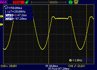
That's a peculiar wave shape, but phones don't normally care much about the wave shape, and it is to within the scope's precision exactly 20Hz! So my careful diagnosis of a frequency problem was evidently wrong. That being the case, why wasn't my phone ringing? I thought to check the voltage.
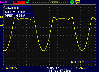
It's 88V, where 90V is nominal and 60V is supposed to be good enough. So this signal should be no problem; but it doesn't work. What's going on? What's wrong?
Look again. Is it really 88V? The signal measured above is 88V peak to peak, but that is not the right way to measure it. A proper ring signal is supposed to be 90V RMS, and there's a ratio of 2.818 between the two. That ratio technically only applies to sine waves, which this isn't, but it's close enough to sinusoidal that we can estimate the signal from the cable modem is approximately 31V RMS; about one third of what it ought to be. No wonder the electromechanical phone couldn't ring!
So I set aside the circuit sketches I'd been drawing of a 555-based 20Hz generator and took a careful look inside the phone. I also, later, managed to find a service manual with a wiring diagram for the exact model of phone I was working on, though by that point I had already reverse-engineered nearly everything I needed to know about it anyway.
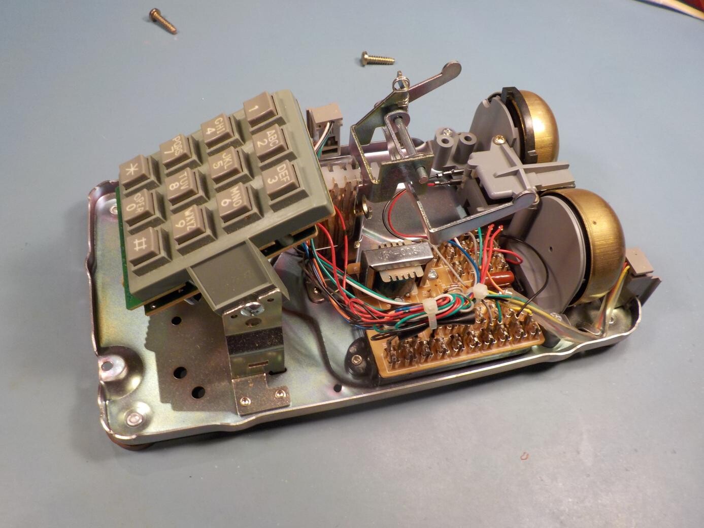
The ringer in this particular phone is just a single coil that connects across the line through a 0.47µF capacitor built into the phone's main connection board. Unlike some other 2500-style phones it doesn't have two separate coils, and it doesn't have a mechanical adjustment for "bias" that might allow it to ring at a lower voltage without any electronic meddling. There is no spring inside the ringer; the clapper that strikes the gongs is a steel ball bearing attracted to a permanent magnet. The magnet's strength, and its position and the positions of the gongs, are all non-adjustable.
If I broke into the phone line between the cable modem and the phone, then I'd be faced with doing a certain amount of logic to detect the various states of the system: on-hook standby, on-hook and ringing, and off-hook. During ringing it'd be necessary to isolate the phone from the cable modem as far as AC was concerned (else risk blowing up the cable modem's output stage with my 90V supply, and that would be a fun one to explain to the cable company's technicians) while still either passing through the 48V DC supply or generating a fresh 48V DC supply of my own. When the phone went off-hook it'd be necessary to detect that using the change in current on the 48V DC, cut off the ringing signal, deal with any spike that might be created by the coil as a result of doing that, and then patch the phone directly through to the cable modem with a relay or similar. None of this stuff is really difficult but it would be enough steps that given the premium cost of one-off electronic development, I wouldn't get out of it for much less than the price tag of the commercial booster device.
Instead, I decided to break in between the phone's connection board and the ringer itself. That way I wouldn't need to deal with the hook switch at all. Bearing in mind that I already had the right frequency coming from the cable modem, only the voltage was too low, I could just amplify the AC voltage that would be sent to the ringer by a factor of about 3. In the on-hook standby state there'd be nothing but DC on the line, which my amplifier wouldn't see (blocked by the capacitor in the phone), and in the off-hook state any AC voltages on the line from me or the other party talking would be much less than ringing voltage, even after amplification, and could be harmlessly applied to the ringing coil (not much different from the situation without a booster). Digging inside the phone instead of building a purely external box turned out to be key to keeping the cost below that of the commercial product - because they have a mass-production discount but are solving a harder problem.
I designed a simple amplifier optimized for boosting a 30V 20Hz signal to about 90V 20Hz, and built it up on stripboard. Here's the schematic of what I finally ended up with. It's a pretty straightforward op amp driving a push-pull Class B amplifier which reduces the input voltage significantly but with large current gain; then I feed the output of that through a transformer of the kind that might be used to produce 5VAC power from 230VAC European mains, running backwards. The output is the high voltage needed to drive the ringer coil. Note the "ground" symbol on the schematic was used for convenience and only represents an 0V reference; I'm not connecting anything to ground myself.
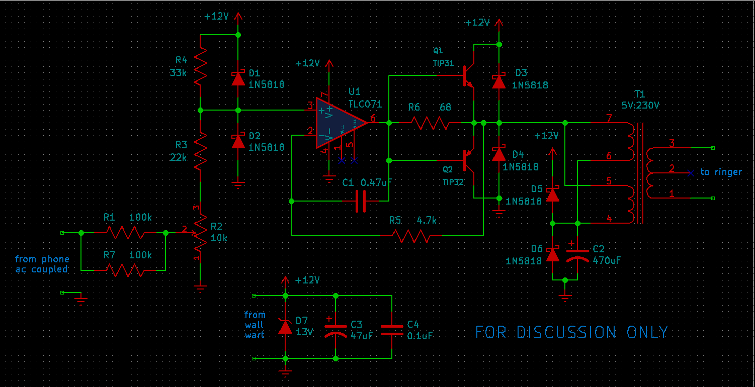
I don't propose to explain the circuit in much detail and I don't particularly recommend that anyone else build one exactly like it from my schematic. It represents a combination of what seemed right for my very specific application, and using as many as possible of parts I already had on hand. It also represents the conclusion of a bit of experimentation, as can be seen by points like the two 100kΩ resistors on the input. Those came about because I started with just one, later decided I needed more gain, and soldering in a second resistor seemed the easiest way to get it. I've put in three pairs of Schottky diodes, and a Zener, for voltage protection not because I really think they're all needed, but because I have a whole lot of the Schottky diodes here (I bought a whole reel for reverse-voltage protection on Eurorack modules), they're cheap, and I'm paranoid about inductive "kicks" from the ringer coil.
Here's a video going through building the booster and some problem solving. Not everything went as smoothly as I'd hoped. In particular, I think I was either using the wrong tool for crimping insulated quick-disconnects, or just using it wrong, because the results I got were embarassingly bad. But I included those parts in the video because I think they make it more interesting.
◀ PREV Green modular, part 5: Behind the scenes || LEDs and analog drivers for them NEXT ▶
MSK 010 Fixed Sine Bank, variant C
US$193.94 including shipping
Comments
I would be interested in seeing your scope output of the final adjusted setup to see the P-P voltage you achieved compared to the input.
I'm not certain there *really* is enough power - that was based on the modem manufacturer's claimed REN, and we already know the manufacturer's claims aren't 100% accurate or else the whole thing would just work. But it seems like the transformer-only plan would be worth a try if I were still looking for a solution. Good thought to try to minimize component count.
Best case, maybe one could even tap the ringer coils, using them as autotransformers, to get them to work at a lower input voltage without any added components at all.
In fact the more elaborate circuit I describe in this article is still in use and still working well, as of mid-2025.