Delta-sigma DACs and CODECs
2023-11-16 electronics digital MSK 014
In the first part of this three-part series on DACs and bit counts, I described what it means to have a certain number of bits in terms of voltage accuracy and signal to noise ratio. Then in the second part I described some ways that DACs are built, basically out of resistors and switches. There are a lot of details along the way, but the big picture in both articles is that you can't really have a DAC with more than about 16 bits. Past that point, the cost of actually building it increases rapidly and the possible benefit drops away. For control voltage generation, the level of absolute voltage accuracy is often closer to 12 bits.
But despite all this, plenty of consumer products do claim to deal in "24-bit" digital audio; and those products contain building-block chips that are described as performing conversion between 24-bit digital audio, and analog signals. You can easily buy such chips and they're not expensive. So how do they exist, and why can't we put one in a Eurorack module to get 24-bit (that is, sub-microvolt) absolute voltage accuracy?
To get a clearer understanding of that, we'll have to go into a few more tricks for building DACs and pushing the bit count higher.
Bringing time into the picture
Suppose you have a microcontroller with a digital GPIO (general purpose input/output) pin which can produce a voltage of either 3.3V or 0.0V. You want a voltage halfway in between, 1.65V. What are you going to do?
One thing you could do would be to make the microcontroller rapidly switch the pin between high and low, so that it is in each state half the time, and then smooth the voltage out with maybe a resistor and a capacitor.
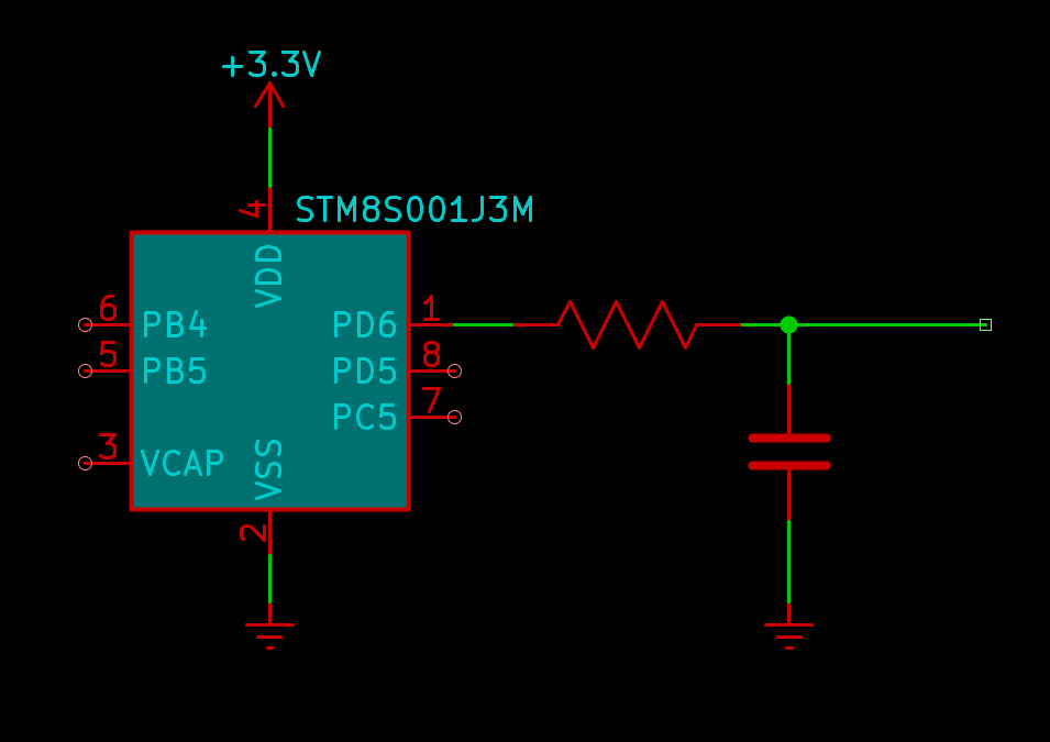
Here the instantaneous voltage at the GPIO pin is always either 3.3V (too high) or 0.0V (too low), but on average it's 1.65V (just right).
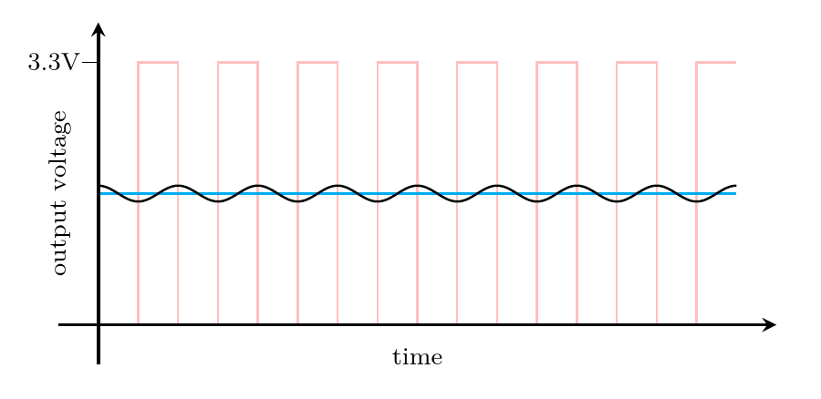
The cyan line in my plot shows the ideal target of 1.65V. The black wave represents the actual output voltage. There's a fair bit of ripple in it as shown, but that's partly an exaggeration to make a readable plot. It should be clear that by choosing a big enough resistor and capacitor, and by increasing the switching frequency high enough, the ripple could be made as small as desired.
Microcontrollers can switch their GPIO pins very fast, and maybe you don't need this output voltage to change rapidly. The resistor and capacitor form a primitive low-pass filter and by making sure that the switching frequency is much higher than the cutoff of that filter, we can set things up so that basically none of the switching ripple makes it through.
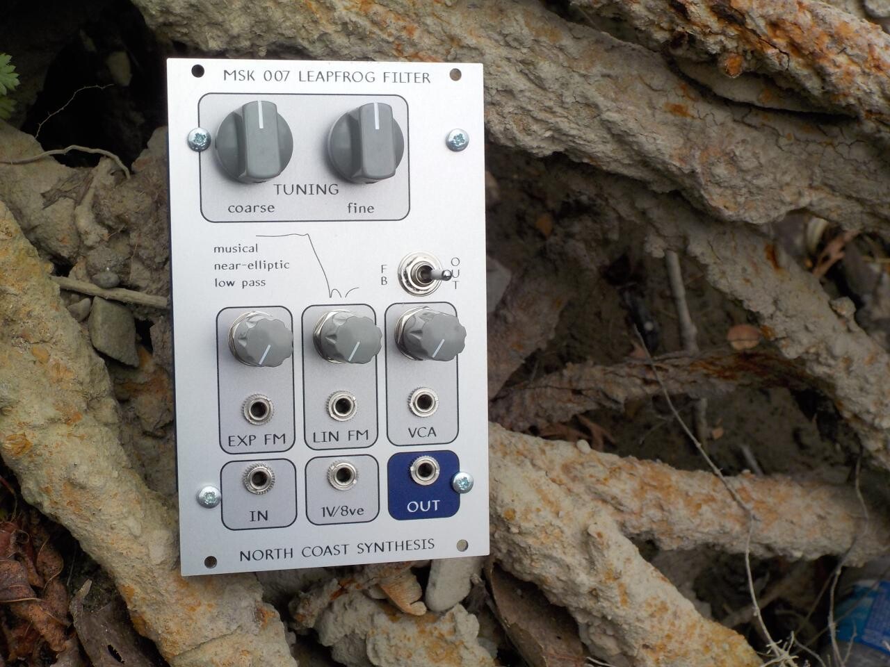
By the way, if you're looking for a low-pass filter somewhat less primitive than a single resistor and capacitor, in a Eurorack synthesizer module, you should consider the North Coast Synthesis Ltd. MSK 007 Leapfrog VCF, which is one of my flagship products. Its unusually steep response curve gives it a unique sound. My ability to create and share educational resources like this series of articles for free, depends on your support in buying my products.
As for the GPIO pin, it wouldn't be very useful to only have a way of generating 1.65V, but this is good for other output voltages too. You can change the switching pattern a little to make the GPIO pin "high" for a larger fraction of the time, and the average output voltage goes up. Make the GPIO "low" for a larger fraction of the time and the average output voltage goes down. We can choose any output voltage between 0.0V and 3.3V just by adjusting the width of the pulses, hence the name of this technique, pulse width modulation or PWM.
With the right software controlling the GPIO pin, this simple circuit can be called a DAC. Digital numbers on the microcontroller representing the desired output voltage turn into an analog voltage across the capacitor. How many bits of accuracy it can be said to have, depends on the nature of the digital signal coming from the GPIO pin: if the microcontroller can drive the pin fast enough and with enough time precision, there seems to be no obvious limit.
PWM comes from basically the same insight, applied to signals, that is so successful with power flows in the design of switching power supply regulators. By bringing time into the picture instead of just focusing on static voltages, we can reduce the reliance on close-tolerance analog components. The values of the filtering resistor and capacitor affect the amount of ripple, not the voltage; so it doesn't matter if they might be 10% off, we just need to make them comfortably large enough. The accuracy of the output voltage is determined instead by how precisely the microcontroller can measure and generate the desired time ratio, and great precision is achievable there.
However, PWM creates two important issues, only one of which we can solve with a more advanced technique. The first and easier issue is that although the switching speed may be kept within reasonable limits, the clock speed increases exponentially with bit count.
With PWM you have at most one chance to choose the output voltage per cycle of the switching pattern; the output can't change any faster than that. (Really, probably less, because this is assuming perfect performance from the analog filter downstream of the switch.) If you want to reproduce a typical DAT digital audio signal (48kHz sampling rate, a very popular choice), then your switching pattern needs at least 48000 pulses per second.
The usual way to implement PWM is to have a counter that increments at some clock frequency which is a multiple of the switching frequency. Then the output is high as long as the counter is less than or equal to the desired output value, at which point it goes low until the counter reaches its maximum and resets. The ratio of the time high to the total cycle is proportional to the comparison value used to drive the switch. The counter has as many bits as the accuracy you want from your DAC, and its clock rate is chosen to produce the desired output frequency.
So if you want an 8-bit PWM DAC with 48kHz sampling rate, then you need your counter to be 8 bits wide, and to increment at a minimum of 28 times 48kHz. That is 256 times 48kHz, or about 12.3MHz.
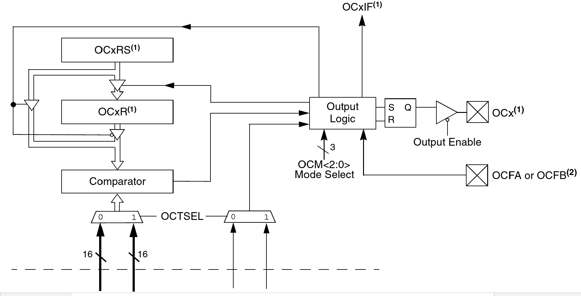
I remember when that number would have sounded like a lot, but running a digital counter at 12.3MHz is no big deal at the present time. Many cheap microcontrollers contain built-in counter peripherals, sometimes purpose-built for PWM use, that can easily run at that rate, and many can even do it in pure software. The block diagram above depicts the "output compare" peripherals built into the MSK 014 Gracious Host's PIC24F microcontroller; it uses them for musical note generation (at much less than 48kHz pulse rate) by activating a mode primarily intended to support PWM.
But the 12.3MHz frequency in my example calculation is for just 8 bits. Every additional bit doubles the ratio between the counter clock and the switching frequency. For 12 bits, the counter would have to run at 196.6MHz to achieve 48kHz sample rate, and that is pushing the limits of commonly-available microcontroller peripherals. For 16 bits, you'd need a counter (and a digital magnitude comparator) capable of clocking at 3.2GHz, which is impractical in a synthesizer module. And it's not really reasonable to go any further.
The tradeoff runs in the other direction too, and that can be a good thing. If you don't need 48kHz sampling but can settle for slower updates of the output voltage, then you can choose a lower pulse rate, a lower cutoff for the filter, and then you can afford to use more bits without making the clock rate unreasonable. The same 12.3MHz clock speed that could support 8 bits of resolution at 48kHz pulse rate, would support 16-bit resolution if we dropped the pulse rate to 187.5Hz, which is still plenty for some control functions. It would have excellent linearity: it might be able to really achieve 16 bits, where the INL of a nominally 16-bit switched-resistor DAC would result in a significantly lower effective bit count. And the PWM DAC would be a much simpler circuit, therefore cheaper.
PWM is used for its advantages, especially cheapness, in many microcontroller applications. It's the usual way to get analog control signals out of an Arduino, with built-in support in the standard libraries. When the speed versus accuracy tradeoff can be made acceptably, it's a valuable technique. But it's seldom usable for audio, where people want both a high sampling rate and a high bit count.
The second and more subtle issue with PWM is that voltage accuracy with PWM is not just some number of bits. Instead it's a tradeoff among speed of changing the output voltage; absolute accuracy of the time-averaged output voltage; speed at which the microcontroller must operate; and the frequency spectra of the signal coming out and the noise added to that signal. It is no longer possible to say that for a given code the PWM DAC produces a given output voltage, and then have specifications about how accurate that voltage is or isn't. It is no longer possible to model the output as sitting at one voltage on one sample and then instantly changing, forming stair-steps over time, to a new voltage when we send a new number to the DAC. Instead, we always have to treat the output as something in motion. We are no longer talking about a voltage but about a signal. This conceptual complexity becomes even greater with the more advanced DAC designs used for today's highest bit counts.
CODECs reproduce signals, not voltages
The ICs that convert digital to analog in a typical consumer audio product are usually not called "DACs" (Digital to Analog Converters) but "CODECs" (COder/DECoders). They incorporate a lot of digital processing in addition to just the part that generates the analog output. They usually go in both directions, digital to analog and back on the same chip. They are designed not just to convert one signal but to provide, in a single chip, most of the interfacing needed by a product like a phone or a music player. A CODEC would have one or more built-in DACs but it wouldn't be just a DAC, and the DACs built into a 24-bit CODEC are not straightforward black boxes with 24 bits of voltage accuracy, because those don't exist.
How the DACs inside a CODEC work is complicated, varies with the specific chip, and may quite possibly be a trade secret that the manufacturer will not disclose in detail. But it usually comes down to some variation of the "delta-sigma" technique, which allows for doing something much like PWM with a smaller ratio between the clock rate and the sampling rate, while preserving a decent signal to noise ratio.
The very high-level overview is that in a delta-sigma DAC (or "sigma-delta"; both terms are pretty common), a digital signal with high bit depth and relatively low sampling rate goes through some kind of digital magic that converts it into a new digital signal with a higher sample rate and lower bit depth. Usually, though not always, the new bit depth is just 1 bit. Then that low-bit-depth signal gets converted by a fast DAC into analog, and the analog gets filtered. The "digital magic" is done in such a way that what comes out of the filter, after averaging out all the high-frequency stuff, will be an analog signal that sounds like the original high-bit-depth digital signal.
Basic PWM actually has the same architecture. The high-bit-depth sample gets changed into a single bit (high or low) by the hardware or software that watches the counter value, at the counter rate which is faster than the sample rate. The GPIO pin can be thought of as a 1-bit DAC, and then its output is filtered. The difference in delta-sigma conversion is that the conversion to a 1-bit signal is done in a smarter way, making better use of the bandwidth available at the clock rate, so that the tradeoffs end up being better.
You may recall that in my previous article I said the resistor-string DAC makes mathematically inefficient use of its switches. It needs 2n switches for an n-bit DAC, and then it always closes exactly one of them at a time; the R-2R DAC is able to improve in some ways by making it useful to close other combinations of switches. Similarly, in PWM there is an inefficient use of time. A complete cycle for one sample of PWM requires 2n clock ticks, but then it only ever changes the digital output twice in that cycle (once at the start, and once when the counter hits the desired output value). What if we could work out a pattern that would be "high" and "low" for the same proportional amounts of time, but switch between them more often? Then we could get better output at the same clock speed.
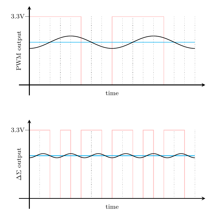
In the above comparison, both 1-bit digital signals are high for 5/8 of the time, corresponding to the code 101 given to a 3-bit DAC. Two complete cycles for the PWM DAC are shown; it goes high twice and goes low twice. But look at the second plot, showing the behaviour of the delta-sigma DAC: it switches back and forth three times as often, resulting in a higher-frequency, lower-amplitude ripple which will be much easier to filter out. (Both ripples are illustrative rather than precisely simulated, but the difference in amplitude and frequency is realistic.)
The general rule is that instead of toggling the output twice per cycle of the sample rate, the delta-sigma DAC decides on every cycle of the clock rate (usually a significantly higher frequency) whether to toggle, such that the average of recent output values will be close to the desired target.
There are several vague points in that description, such as how far back "recent values" go, what weighting is put on the average, and what "close" means. Real implementations vary a lot on these points, and the choices made about them interact with the choices made about exactly what kind of analog filter to put downstream of the 1-bit output. It is also possible to use a DAC with more than 1 bit (such as 2 or 3) between the digital logic and the analog filter. And there can be some important non-obvious refinements, such as deliberately adding some extra noise in the lowest bits of the digital processing to prevent it from getting locked into a short loop which would create frequency spikes in the output signal.
The point is that by making much more frequent changes in the output bit, the ripple and other error is made smaller and higher-frequency. That makes better tradeoffs possible: compared to PWM, we could choose a higher cutoff frequency for the filter (which allows faster sampling), or a lower clock frequency (which allows better resolution), or keep the same sampling rate and resolution but be able to cut costs elsewhere, such as in the analog filter.
If you change the target voltage for a delta-sigma DAC, you have the opportunity to make the output change much sooner than with PWM. With PWM, you basically have to wait until the next sample cycle; but a delta-sigma DAC asked to produce a lower target output voltage can drive the output low as soon as the next clock tick to start converging on the new value. Whereas PWM couldn't possibly reproduce an output signal at a higher frequency than half the sampling rate (by the Nyquist Theorem), and the sampling rate was limited to 1/2n of the clock rate, with the delta-sigma DAC the highest output frequency is related directly to the clock rate instead. That allows shrinking the clock rate from what a simple estimate based on sample rate and bit precision would otherwise imply.
But if you really want extremely precise DC voltages, you still have to wait a lot of clock ticks for the voltages to average out.
That's why I emphasize that CODECs, with their typical delta-sigma DACs, do not reproduce voltages; they reproduce signals. If you read the specifications for a CODEC, they won't be quoted in terms of INL and DNL like the specifications of a DAC intended for DC control voltages. They usually won't even be quoted in terms of bits. Although the CODEC may be called a "16-bit CODEC" or a "24-bit CODEC" or even a "32-bit CODEC," those bit counts refer to the format of the digital data it processes, and maybe, if you're lucky, the widths of some of the calculations it makes. The DAC itself is not really well-described by a number of "bits." Instead, the DAC will have specifications in terms of analog signal parameters like bandwidth and signal to noise ratio, from which you can try to calculate an equivalent number of bits if you want, but that may not be the best way to understand what's going on.
Here's a clip from the data sheet for the Renesas Electronics DA7212, a typical low-end CODEC chip I selected more or less at random from Mouser search results. It's configurable for 16, 20, 24, or 32-bit data modes, and it offers stereo (that is, two channels) conversion between analog and digital in both directions. It also has added features like analog amplifiers for interfacing to microphones and earbuds, a built-in equalizer, a primitive synthesizer called a "beep generator," and some power-supply and power-on system control stuff. The idea is that you could build this plus a microcontroller into a portable music player, and you'd need very little other circuitry.
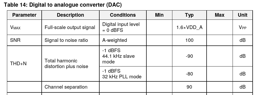
There is nothing like an INL or DNL for the DAC mentioned on the CODEC data sheet, from which we might try to compute DC voltage accuracy. DC voltage accuracy is not what this chip is all about. The data sheet doesn't even actually mention a specific number of bits for the DAC at all, although the ADC is described as "24-bit" and the registers in the digital interface allow for writing 24-bit words to the DAC.
Someone who built this chip into a product would probably use the register width as an excuse for claiming the product had "24-bit" digital to analog conversion. A less honest manufacturer might switch the interface into 32-bit mode, never mind that the bottom 8 bits will be ignored, and call it "32-bit audio." But being able to write 24 or 32 bits to the DAC absolutely doesn't mean you could use this chip as a black box to generate DC voltages with the sub-microvolt precision someone might thoughtlessly expect from the phrase "24-bit DAC," let alone the sub-nanovolt precision implied by "32-bit." Note that 32 bits of absolute voltage precision is much better than even the liquid-helium-cooled primary voltage standard costing hundreds of thousands of dollars could achieve (27.6 bits).
Instead, the only correct way to think about the "accuracy" of the output of a product like this CODEC chip, involves reading what the data sheet actually says. It says the signal-to-noise ratio is (subject to a lot of small print) 100dB, A-weighted. That means the output signal, not voltage, under optimal conditions, will sound about as good to a human ear as if it were coming from a theoretically perfect 16-bit black-box DAC (96.3dB). Ears themselves are only about that good, so we can't realistically expect audio to be any better. The term "A-weighted" means that this specification is preferentially counting frequencies at which people's ears are more sensitive - and in particular, people can't hear a frequency of 0Hz, that is DC, so DC doesn't count. The manufacturers of this chip make no promises regarding the DC voltages it produces.
And to get 100dB of signal to noise, you have to be selective about what counts. This chip only has 90dB of channel separation, so if you have a signal in the left channel that you don't want to hear in the right, then right there you've lost 10dB of your "accuracy," dropping the effective bit count from 16.6 to 14.9. If you count harmonic distortion, then depending on whether you use "PLL mode" it might be as bad as 80dB, which drops the effective bit count to 13.3. That's a much less impressive number than "24-bit." But it's a perfectly reasonable quality level for the digital to analog conversion in a cheap portable audio player, which is what this chip is meant to do.
The digital to analog conversion in a personal computer's audio interface ("sound card" to old-timers) is nearly always also done by a CODEC chip, and that's what people miss who participate in the annual sport of posting "List of DC-coupled audio interfaces <year>" threads on synth fora. I've written before about AC and DC coupling, and it's certainly true that if your audio interface is AC-coupled, then you're not going to get accurate DC voltages out of it, nor any DC voltages. But the real issue isn't just whether they included a capacitor or not, and the "mods" people sometimes try to make by finding and removing the AC-coupling capacitor in an audio interface, are usually misguided. An audio interface based on a 24-bit CODEC is designed to reproduce signals, not voltages. No amount of removing capacitors will change it into something capable of accurately reproducing voltages because that's just not what delta-sigma DACs do. The few commercial interfaces that really are meant for control voltage use are based on very different DAC technologies specific to their intended purpose, and DC coupling is only one of the many details involved.
To summarize this series of three articles: I've gone through several different views of what "bits" really mean with respect to DACs. There is the number of digital ones and zeroes that go into the converter; but then there is also the precision of the voltages that come out, which are often less precise then the number of bits of input would imply. I've discussed different specifications for the voltage accuracy of a DAC, and, especially in the second part of the series, how DACs with different architectures tend to perform on those specifications. In this third part, I've described CODECs and the DACs usually built into them, which are designed to produce signals, not voltages, and so have different kinds of specifications not directly comparable to the specifications of DACs designed for precision DC use.
My biggest hope for this series - as well as selling my own modules, of course - is that we can put to rest calls for extremely high bit counts in synthesizer control voltage generation. Twelve bits is plenty for that application; and if you see a product claiming to contain "24-bit" DACs, you should know that that is necessarily talking about a different quality specification, not directly relevant or comparable to the bit count of a DC voltage generator.
◀ PREV DACs, resistors, and switches || Build your own commercial module part 1: the design concept NEXT ▶
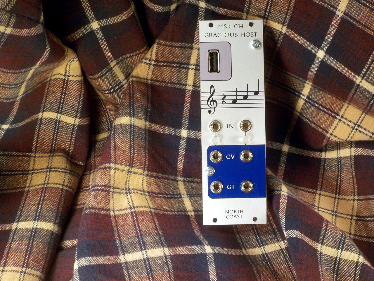
MSK 014 Gracious Host
US$244.68 including shipping
Comments
I'd be interested in your analysis of the popular 'high-end' ΔΣ DAC ICs from Asahi Kasei Microdevices (AKM) and ESS Technology.
It manages to output both high quality audio and accurate DC voltages using a delta sigma. This includes accurate V/Oct CV over 10 volts.
The specs listed by the company are a bit misleading, "24 Bit DAC" but they also say its a delta sigma, so not that bad. I've heard they just use a calibration routine to get the accurate DC.