DACs, resistors, and switches
2023-11-15 electronics digital MSK 014
In the previous entry, on DACs and bit count, I talked about the relation between how many bits a DAC has and how accurate its voltage can possibly be, both at the limits of modern technology (liquid-helium-cooled superconducting Josephson references) and in the abstract for theoretically perfect DACs. In this entry, let's look at the details of some more realistic DAC designs that would actually be used in Eurorack modules.
The resistor-string DAC
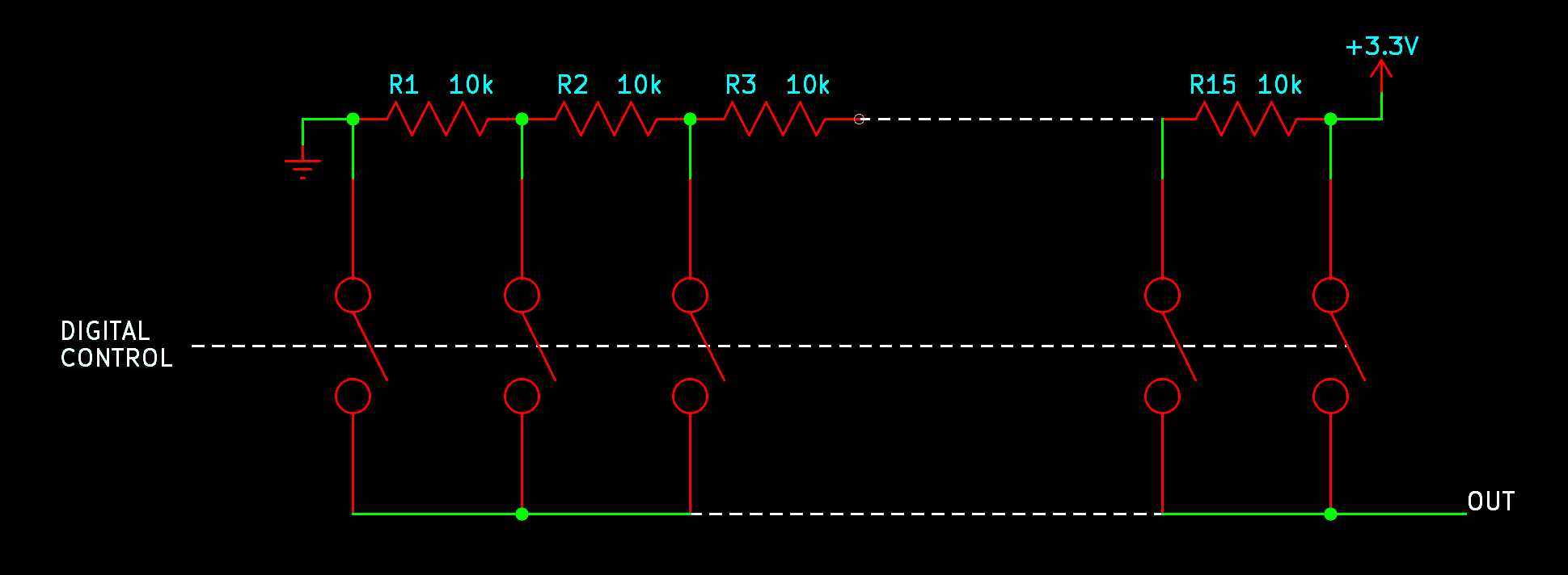
Think about what a DAC does: it has a fixed, known selection of different voltages it can produce at the output (one for each code), and depending on the input code, it presents one of them at the output. A straightforward way to build something like that would be to generate all the voltages at once with a multi-output voltage divider - just a string of equal resistors - and then use a bunch of switches to select which one should appear at the output. The control system for the switches is simple digital electronics and, although not shown in my diagram, it's not difficult to design or build that part unless you are really pushing hard on specifications like speed. In my example, there are four input bits, so there are 16 different codes, 16 switches, and 15 resistors to generate the voltages.
This kind of DAC basically works. It can be very fast because the digital logic is simple and the electronic switches open and close fast. But there are a couple of issues that mean it's not the end of the story, and not universally used in practice.
First of all, resistor tolerance comes into play. I routinely use 1%-tolerance metal film discrete resistors in my commercial Eurorack module designs. But we want DACs to be building-block ICs, with all the parts built onto the chip, and it's difficult to build precise resistor values on an IC. The resistors built onto an IC might be 20% tolerance, meaning that where it says 10kΩ on the circuit diagram, the true value of the resistor could be anywhere from 8kΩ to 12kΩ.
Suppose all the resistors in the left half of the chain (up to and including R8 in the middle) are actually 12kΩ and all those in the right half are 8kΩ. Then the voltage near the middle of the chain will be significantly higher than it should be. For most codes, the DAC will produce an output voltage higher than we would expect from basic theory. The worst code with these example values is input code 0111, where the output voltage should be 1.54V and is actually 1.87V, a difference of 0.33V. The error resulting from resistor tolerance is three times, and added onto, the unavoidable error resulting from the fact that it's a 4-bit DAC.
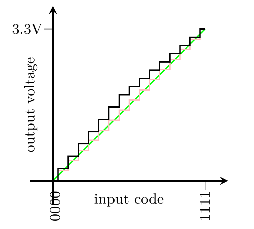
In the diagram, the green line represents perfect reproduction of a desired analog voltage. The faint pink stair-steps show the best reproduction possible with a 4-bit DAC, hitting desired voltages to within ±0.11V on a 3.3V output range. But the black stair-steps show the performance of my example resistor-string DAC built with 20% resistors. At its worst, it is off from the pink ideal voltage by 0.33V; that is 9.5dB worse than the theoretically ideal 4-bit DAC. We have lost about 1.6 bits of performance because of the resistor tolerance; the 4-bit DAC is only as accurate as an approximately 2.4-bit DAC.
There are different ways to describe the gap between a theoretically ideal DAC's performance, and what is actually achieved by a real one built with imperfect components. In the data sheet for a building-block DAC chip you will often find separate specifications for integral nonlinearity (INL) and differential nonlinearity (DNL), either of which are usually measured in multiples of the least significant bit (LSB).
The LSB is the size of the (theoretically ideal) step between two successive output values. The DNL is the worst-case difference between that and the real step between two successive codes. In my example, the step size ought to be 0.22V per count, and the worst pairs of consecutive digital input codes are only 0.16V apart, so the DNL is (0.22V-0.16V)/0.22V or 0.27 LSB. That specification is relevant to how accurately the DAC can reproduce small AC signals, and a value of 0.27 LSB is pretty good (better than most commercially available DACs). Resistor string DACs in general often have good DNL performance.
But DNL only describes the accuracy of a voltage step relative to nearby steps. If those errors can add up across many steps, as in the diagram of my example, then the absolute voltage for a given output code may be much further from the theoretical ideal than the DNL suggests. The other nonlinearity specification, INL, describes that kind of absolute error: it is the worst-case error between the voltage for a given code, and the value we would hope for from a perfect DAC with the same range and bit count. The INL specification doesn't count the unavoidable error associated with the bit count, which even a perfect DAC would have. It's measured relative to a theoretically perfect linear DAC with the same number of bits.
Usually manufacturers allow for separately trimming out an overall scaling and offset error, so INL represents the error between the DAC and some perfectly linear function, not necessarily the ideal linear function. At high bit depths, manufacturers also play games like allowing the DAC to deviate from linearity in the first and last few codes at the ends of the scale, so INL may not be quite valid rail to rail. You have to read the small print on the data sheet carefully.
In my example, the INL is 0.33V or 1.5 LSB. From the INL it's possible to compute an effective bit count describing how many bits a theoretically perfect DAC would have, if it had the same DC accuracy as the real DAC we're considering. With an INL of 1.5 LSB we are losing about 1.6 bits. (The formula is bits lost = log2 (1+INL).) So our example 4-bit DAC is, in one important sense, only as accurate as a 2.4-bit DAC.
Good chip designers have ways of limiting these inaccuracies. Although 20% is a realistic value for the absolute tolerance of resistors on an IC, it's not actually necessary for the resistors to all equal 10kΩ for this design to work. It's only necessary for the resistors to equal each other. The relative tolerance of integrated resistors - that is, the difference in resistance between two resistors side by side when they are supposed to be the same value - can often be much better than 20%. So we would start by optimizing the manufacturing process for relative tolerance.
We can test DAC chips as they come off the line and throw out any that happen to be especially bad; that is already done in semiconductor manufacturing for other reasons so it may not really increase costs much. It is also possible, though expensive, to "laser trim" the resistors: build the chips first with resistor value targets lower than desired, then test each chip and selectively blast away parts of the resistors with a laser, to increase their resistance and bring them more accurately to the desired values.
For every additional bit we have to cut the resistor tolerance range in half. Going from 20% to 10% might be no problem; maybe with laser trimming we can go as far as 1%; but that's only about another four bits beyond the example. If we want a DAC with more than eight bits that really works at more than about 8-bit DC accuracy, the basic resistor-string technique with resistor tolerances we can really achieve, is going to be challenged. This is far from even the 16-bit level of the old Compact Disc standard, let alone the 24-bit level that present-day Eurorack users think they want.
And there is another problem: the number of resistors and switches in this design doubles for every additional bit! At the 8-bit level the number of these is a few hundred, which is still reasonable to put on a chip. But if you wanted to build a 16-bit DAC of this general design, you'd be looking at tens of thousands of bulky integrated resistors in each DAC channel, and an impractically large and complicated IC. Sixteen-bit resistor-string DACs do exist, such as the Texas Instruments DAC8560, but they are expensive and require some compromises; at that bit depth other technologies are more popular.
The cost of doing laser trimming similarly explodes because it is proportional to the number of resistors you will trim, so that technique is impractical for any but the smallest resistor-string DACs. There are other issues, such as charge injection from the switches, that would come into play once the bit count got high enough, but they probably wouldn't end up being the deciding factor in an already-impractical design.
Resistor-string DACs are used in situations where their advantages are important. If you want a DAC with a low bit count (like, no more than four bits) and you want very high speed, it might make sense to use this design. For instance, something like that might be used for generating IF signals in a software-defined radio. On the other hand, a "digi-pot," used to allow computer control of an analog circuit which might otherwise have involved a physical potentiometer, is basically a resistor-string DAC running at low speed. The digi-pot benefits from the resistor string's low DNL error, which makes the sweep of control values smooth; and from the fact that the output can be easily presented as two variable resistances instead of a pure voltage. Digi-pots usually max out around 8 or 9 bits.
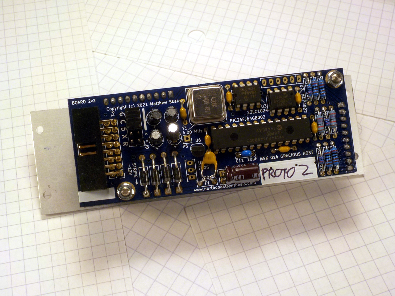
In the Gracious Host, I use a Microchip MCP4822 dual 12-bit resistor-string DAC. Each of the two channels on the chip has to contain over 4000 integrated resistors (which consume much more space than integrated transistors) for the resistor strings alone, and a similar number of transistor switches. It is a popular chip, not too expensive, from a decent manufacturer, that many other designers besides me have also used in Eurorack modules. Using it is an uncontroversial decision, among people who know building-block DAC ICs.
Now, hold onto your pants. The MCP4822's worst-case INL specification is 12 LSB. That'd be mostly the effect of resistor value tolerances. Although Microchip's data sheet says that it will typically be a lot more accurate than that (2 LSB typical INL), all they really promise is the chip's absolute output voltage will be within 12 counts of the voltage it theoretically should be for a perfectly linear 12-bit DAC. From the formula I gave earlier, this INL specification means a loss of 3.7 bits. The worst-case effective bit count for this chip is only 8.3 bits. With the voltage scaling used in the Gracious Host, the worst-case INL translates to an accuracy loss of about 17mV relative to a theoretically perfect 12-bit DAC, or about 21 cents of pitch error on a V/oct control voltage. That's pretty bad.
Or is it? There's actually even more going on here. Before going into how the Gracious Host improves on the INL specification of its DAC chips, let's talk about another DAC design.
The R-2R DAC
Thinking about it in general mathematical terms, part of the problem with the resistor-string DAC is that we are using the switches inefficiently: for each output code we close exactly one switch, and so to get 2n possible states for the circuit, we need 2n different switches. What if we could set things up so that it would be useful to close more than one switch at a time? Then we might be able to use fewer switches, and fewer other components like resistors.
I mentioned earlier that a DAC might reasonably be just a resistor network: some kind of glorified voltage divider that applies the digital input voltages to the output with different amounts of attenuation so that the overall total is the right analog output voltage. It might look a lot like this.
(Trademark considerations preclude my including a picture here of R2-RDAC, Interface Droid. You'll have to use your imagination.)
The switches along the top exist to translate the possibly-inaccurate digital voltages into exactly 0V for logic 0 and exactly 3.3V (or as accurately as whatever reference source is supplying that line) for logic 1. Then these feed into a network of resistors that computes the desired output voltage.
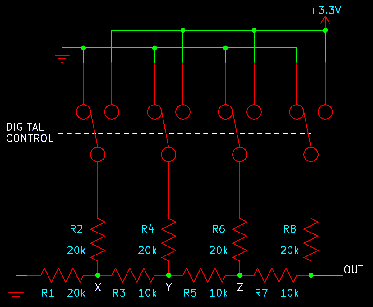
The resistor network is best understood by thinking in terms of equivalent circuit impedance, and the fact that we want each successive bit to have twice as much influence on the output as the last. It is called an R-2R network because all the resistors are either a fixed base value (R, in this case 10kΩ) or twice that (2R, 20kΩ). Note that "R-2R" does not stand for "rail to rail" here; I have seen that error even on a Texas Instruments data sheet.
Consider just R1. It goes to ground, and it always presents to the point labelled X a voltage of 0V with impedance of 20kΩ.
Now consider just R2 and the attached switch. The switch connects to either 0V or 3.3V, assumed to be pure voltage sources, and then R2 brings the impedance to 20kΩ. These two components present at point X a voltage of either 0V or 3.3V, like the output of a 1-bit DAC, with impedance also 20kΩ. Combining these with R1, we have a voltage divider that cuts the voltage in half, so it can be thought of as a 1-bit DAC with output impedance of 10kΩ (two 20kΩ resistances in parallel) and range 0V to 1.15V.
Now consider R3, in series with the output of that DAC. It raises the impedance of everything to its left to 20kΩ (10kΩ in series with 10kΩ) as seen at point Y. Then we have R4 and its switch, which are like another 1-bit DAC with output impedance 20kΩ. These two DACs in parallel form a 2-bit DAC. The first bit has exactly half as much influence on the output as the second bit, and the overall impedance up to this point (considering R1 through R4, as seen at point Y) is 10kΩ again.
The pattern continues: for each bit we're adding a 10kΩ resistor in series, which raises the impedance to 20kΩ, and then we're adding a new 1-bit DAC in parallel, bringing the impedance back down to 10kΩ. Each time we do this we cut in half the contribution of all previous bits compared to the new bit. We end up with pretty much exactly the input-to-output function we want, with bits influencing the output in a binary pattern.
It seems like you could build this circuit for as many bits as you want.
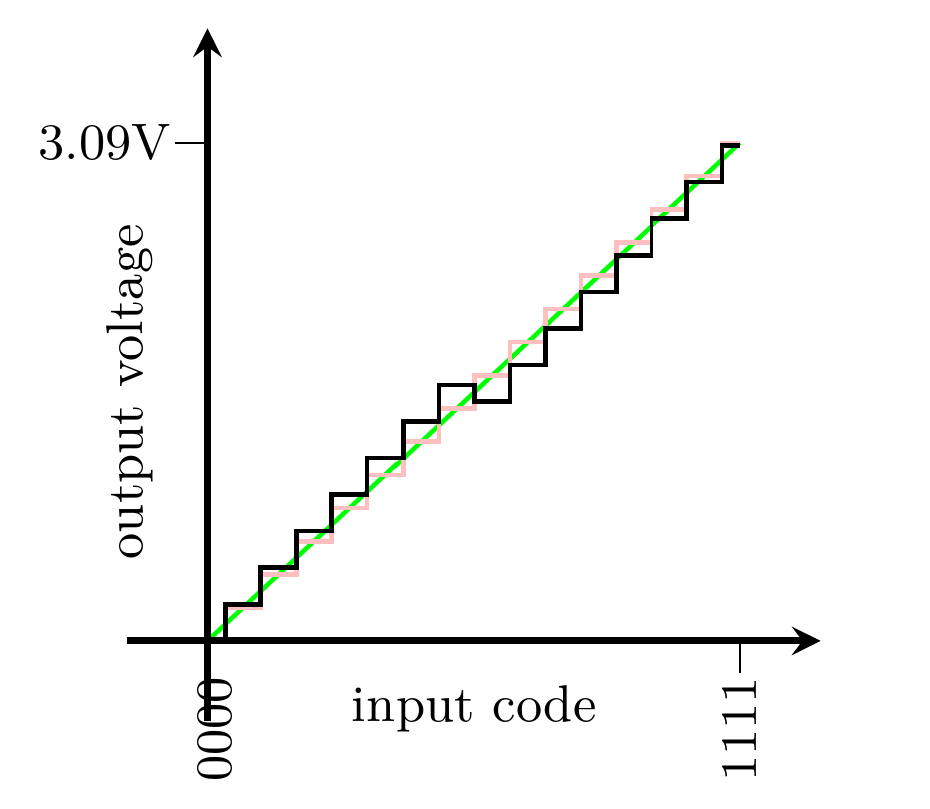
One small gotcha is that the maximum output voltage from this arrangement is not quite 3.3V because there will always be that resistor at the left going to ground, so instead of an output range from 0V to 3.3V as in the resistor-string case, in the four-bit R-2R example the range is really 0V to 3.09V, which is (15/16) times 3.3V. But that distinction will be negligible once the bit count goes a little higher, and there are ways to compensate for it if desired.
The overwhelming advantage of the R-2R design is that instead of needing a number of resistors and switches that doubles for each input bit, here we only need two resistors and a (double-throw) switch per bit. Adding one bit adds two resistors instead of multiplying the number of resistors by two. So for any significant number of bits, R-2R will be a simpler circuit, and this advantage grows with the number of bits.
What about resistor tolerance? That is still a significant issue, but it is an issue for a smaller number of resistors. Not only are there fewer resistors in this design overall, but only a few of them are really critical.
Suppose R1 is off-value by 20%. Its influence on the final output voltage gets cut in half when it is put in parallel with R2, and then again when R1 through R3 are put in parallel with R4, and then again when we add R6, and again at R8. At the final output it makes much less than 20% difference. It doesn't really matter much to the INL if R1 is off-value, even by quite a lot, because its final influence on the output voltage is so small.
The value of R8 makes a big difference to the final output, but that's only one resistor. Similarly R7 and R6, though they already have only half as much influence. The other resistors have rapidly decreasing amounts of influence as we move further left on the diagram, and soon become unimportant. If we're going to put a lot of effort into getting good resistor values and doing things like laser trimming, we can focus the effort on just the last few resistors. Although the necessary precision still increases with additional bits, the number of resistors whose values are critical does not grow rapidly. Then it is reasonable to use relatively expensive techniques for getting those few values right, which would never be practical in a resistor-string DAC where many resistor values matter.
Using an R-2R approach makes it possible to build a DAC with pretty good DC accuracy and high speed. It's still necessary to have some high-precision resistor values, and the necessary precision still increases with increasing bit depth. This approach allows pushing a few more bits beyond the limits of the resistor-string approach, or in the alternative, it may allow for better INL at a given number of bits.
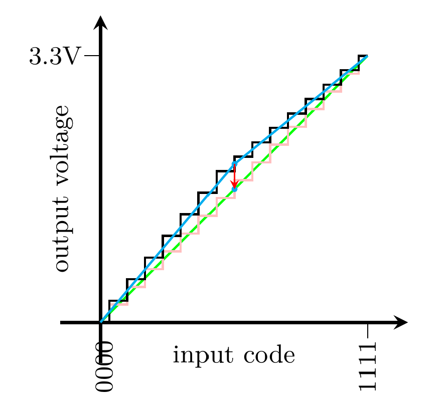
This next plot shows what can happen if we build the above 4-bit R-2R circuit with 10% resistors, in a case where R1 to R7 are 10% low and R8 is 10% high. This is better resistor tolerance than I used in my resistor-string example. I am assuming that because there are fewer resistors in the R-2R DAC, we can afford to spend more effort on getting their values right, and I wanted to choose values that would clearly distinguish the strengths and weaknesses of the two designs.
Between the codes 0111 and 1000 there's a stair-step in the wrong direction. This happens because the most significant bit has too little influence and the others have too much, so switching from all the low bits to just the high bit means switching from the voltage being a little too high, to the voltage being a little too low, enough to overwhelm one step's worth of voltage change. A mathematical way to describe it is to say that the input to output function is "non-monotonic": it does not always go upward or always downward. Increasing the input code might actually decrease the output voltage.
This R-2R DAC has better absolute voltage accuracy than my example resistor-string DAC. The black stair-steps stay closer to the green line. If we consider output codes one at a time, the R-2R DAC seems to be doing better than the resistor string at staying close to the performance of a theoretically perfect 4-bit DAC. But the R-2R DAC does that weird backwards step, which the resistor-string DAC would never do, and that might be a serious problem in some applications.
In terms of data-sheet specifications, we can say that this DAC has INL of 0.8 LSB, giving better voltage accuracy than the 1.5 LSB of the resistor-string example. But the DNL for this DAC, representing the relative error between adjacent codes, is 1.5 LSB, much worse than the resistor string's 0.27 LSB.
That is why R-2R DACs do not completely replace resistor-string DACs. They use fewer components, making it easier to optimize the INL, but it usually means a trade-off for significantly worse DNL. In particular, they can produce non-monotonic output, which is basically impossible for a resistor string. They still require at least a few precision resistors, and that requirement gets worse at higher bit counts. The effective bit count will still be less than the number of bits suggested by the circuit topology. An R-2R DAC can push the effective bit count past what would be possible with a resistor string, but it will still have some trouble achieving 16 bits of real absolute voltage precision, and to get those last few bits, you may be accepting some compromises like the possibility of non-monotonic behaviour, which may not be obvious at first glance.
Many building-block DAC ICs for moderately high bit count, like say the Texas Instruments DACx0501 family (12, 14, or 16 bits), use an R-2R design. Those particular chips claim DNL and INL specifications of 1 LSB each (the DNL, in particular, meaning that they can just barely guarantee monotonicity). Several manufacturers offer "multiplying" DACs, which are basically just the switched R-2R network ready to have support circuitry like op amps added. Then instead of necessarily taking a plain voltage output, you can build an amplifier where the DAC directly controls the gain, which is often useful.
Trimming in software
DACs are always driven by some sort of digital electronics, usually a full-blown computer of some sort, and in this day and age, digital computation is cheap. So can we do something on the digital side, spending a bit of computational effort, to compensate for the deficiencies of the DAC?
If the DAC chip is something like an MCP4822, with an INL of 12 LSB, that means sometimes when we ask for a given code, the DAC's output might be a voltage up to 12 counts higher or lower than we asked for. So in such a case, why not just ask for a different code? If the DAC's output is going to be 12 counts high, and we know it, then we could subtract 12 from the code before sending it to the DAC, and then the DAC's output would end up just right.
The general technique is for the computer to store a model of what voltage comes out of the DAC for each code, and then choose whatever code will produce the desired voltage, even if the choice isn't linear. For voltages where the DAC's output is a little high, it chooses the code a little lower to compensate, and vice versa. This approach can be called software trimming: it is something like laser trimming, but implemented in software.
In principle, software trimming can be done with any kind of DAC, and it can dramatically improve accuracy as long as the model accurately represents the error in the DAC's output. It's both more necessary, and more effective, at higher bit counts. What kind of model is appropriate may be different for different kinds of DAC. It may be necessary to implement some kind of calibration or adjustment procedure, measuring the DAC's real output voltages for different input codes, in order to derive the best model for that particular individual DAC chip - because different chips of the same type will often have their errors in different places. It also is necessary that the DAC implements some input-to-voltage function consistently, because if the chip changes over time, then the model will end up wrong.
For resistor-string DACs, the error often tends to vary slowly and smoothly across the voltage range. In my example, the output voltage is pretty good at the top and bottom of the range and bulges up in the middle; so the model will subtract more from the digital value near the middle of the range. In higher-bit-count resistor-string DACs, the error often looks like a wave, going up and down just a few times over the entire voltage range. It's very popular to model these errors with a piecewise linear function.
With an R-2R DAC similar compensation is possible, but some other model - for instance, piecewise constant broken down by binary fractions of the range - might give better results than piecewise linear.
The MSK 014 Gracious Host uses a piecewise linear model appropriate to its MCP4822 resistor-string DAC. After manufacture or kit assembly, there's an adjustment procedure during which the firmware indirectly measures the true voltage of the DAC output at ten calibration points corresponding to nominal half-volt intervals from 0.5V to 5.0V output (an eleventh point at 0V is used as an offset reference). It stores the measurements in flash memory to build the error-correction model. Then whenever it has to produce a pitch control voltage, it checks the calibration values on either side of the desired voltage and interpolates linearly between them. Details of the calibration procedure, including the tiny assembly-language multithreading kernel I wrote to allow for calibrating both channels at once, are in the "calibration" chapter of the Gracious Host Programmer's Manual.
The chip in the Gracious Host is nominally a 12-bit DAC, but loses about 3.7 bits of voltage accuracy to its 12 LSB INL specification. Software trimming brings back most of the lost accuracy (hard to say exactly how much without a bigger experiment than I can reasonably do), making the final voltage accuracy good enough to exceed the precision most Eurorack oscillators can achieve.
The big disadvantage of software trimming is that it necessitates a per-unit calibration step. It also depends on a close match between the model chosen, and the actual error profile of the DAC in question. But it does work, it can remove errors that would be expensive to remove any other way, and it has the hidden advantage of also allowing for correction of other errors in the system beyond the DAC. For instance, if an analog VCO exhibits the common pattern of going a little flat at high frequencies, and you calibrate your Gracious Host using that oscillator at a standard tuning-knob setting, then it will automatically tweak the codes upward a little at high voltages to compensate for the oscillator's flatness, resulting in actual pitches even more accurate than a perfectly linear DAC would give.
I've described a couple of approaches to generating voltages with DACs consisting of resistors and switches. When used to best advantage, possibly with software trimming on top of the capabilities of the hardware, these techniques can achieve DC voltage accuracy up to about 16 bits, and maybe just a little beyond that. But we still don't know why CODEC chips are routinely sold on a claim that they operate at "24 bits." The next level of performance, and the ways in which the "24 bits" of an audio CODEC are not really the same kind of bits, are discussed in the third part of this series: Delta-sigma DACs and CODECs.
◀ PREV DACs and bit count || Delta-sigma DACs and CODECs NEXT ▶