Free EDA software rundown
2017-08-20 design electronics review software
The MSK 008 Octave Switch is planned to launch tomorrow and I've already posted the manual; so I thought it would be fun for this week's Web log entry to introduce some of the software tools I use for producing, and especially for documenting, module designs. My designs are free, my roots are in the free software community and my values emphasize all aspects of free speech, and so I try to stick to free software in running my operation. The title says EDA software ("Electronic Design Automation") but in fact this list covers some other engineering functions too, that people don't usually think of as EDA.
KiCad
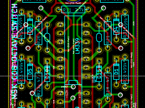
KiCad is a multi-function suite of EDA software from CERN. It covers "schematic capture" (i.e. getting the circuit design into a machine-readable format), PCB design, and some related functions. There are simulation features in the newest version but I haven't tried them in any serious way yet; see my comments on other simulation stuff below. After trying several, KiCad is my current preference for general EDA stuff, and it's KiCad files you will find in the source code packages for my current modules. As with pretty much all such packages, there are some aspects of the user interface that will be unfamiliar to those accustomed to present-day desktop computer user interfaces. A lot of that comes from the heritage of earlier CAD and EDA software, which predated the current generation of windowing UIs; KiCad is heavily hotkey-based, and I usually use it with one hand on the keyboard and the other on the mouse.
QCAD
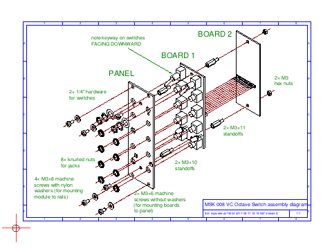
One thing I've learned the hard way in developing my products (and will probably write more about another day) is the critical importance of mechanical design. The electronic side, covered by software like KiCad, is much easier than people imagine; what really costs development time and money is counting millimetres and making sure everything will be physically the right size and fit together properly. QCAD is a 2D drafting program which I use for creating mechanical drawings of the things that go into a module to help sort out those issues. Like KiCad, it has some user interface peculiarities which take some getting used to - especially to do with selection of objects. But as someone who studied real mechanical drawing with a T-square Back In The Day, I found the workflow intuitive once I started thinking about it in terms of how I would draw with a physical pencil: many operations in QCAD like laying out construction lines and then erasing the bits that aren't part of my drawing, are exactly analogous to what I would do on paper.
The organization that sponsors QCAD is trying to make money by selling 3D and CAM integration features. I hope they can stay in business, but my general allergy to "demo" versions means I wouldn't buy those products. The 2D package stands pretty well on its own and doesn't seem to be crippled for demo purposes.
Qucs
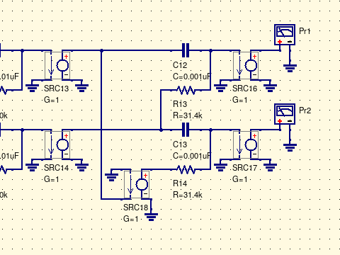
Qucs is a circuit simulator with a graphical interface. It's good for playing with circuit ideas as one might with a breadboard, an important difference being that in the simulator one can use ideal components and not have to worry about a lot of details relevant in real life. I often use Qucs in the early, conceptual stages of a design, to get a quick feel for what circuit topologies are or are not worth pursuing.
Circuit_macros
Excellence in technical documentation is part of the North Coast way of doing things, and so it's more or less automatic that I use LaTeX to typeset the user/build manuals for my products. I've given a couple of talks at TeX Users' Group meetings - watch my presentation from last year about astrological charts if you have some spare time. When it comes to putting schematics in LaTeX documents, there are a number of different software choices available. I prefer Circuit_macros mostly for the visual quality of the results; many of the others use symbol styles I don't like. Circuit_macros uses a fairly complicated workflow, with the circuit defined in an M4 file which then has to be processed into TeX source code for inclusion in a document, but it's reasonably easy to automate and integrates well with the GNU Make workflow I'm already using for other reasons.
昨年日本語でCircuit_macrosについてブログを書きました。
Ngspice
The SPICE must flow! Qucs, with its graphical front end, is nice for playing with ideas at an early stage, but sometimes it's necessary to do a more serious and automatic simulation study on a more fully developed circuit design. For instance, sometimes I want to make sure that my design will work in all cases as components assume different values within their tolerance ranges, and the sheer number of cases makes it tricky to test that by any manual process. For that kind of thing I usually use Ngspice, which does circuit simulation in a command-line context.
Ngspice is one of several current packages descended from the old traditional Berkeley SPICE. To use it, you describe your circuit in a programming language that partakes heavily of FORTRAN, and then run the simulator on your input "deck" (because it's punch cards, eh?) and look at the result. There is an interactive mode, but by the time I'm ready to use Ngspice I'm usually doing things like running a thousand simulations with different parameters, so I'm often running it from some kind of script that I write to set different parameters and collate the results. This is usually a big operation, which is why I don't reach for Ngspice first, but to answer the questions that require larger-scale simulation studies I can't do in Qucs, there's not much better way to do it. One of the really nice things about this or any similar SPICE derivative is that manufacturers often provide SPICE-compatible models for their devices, so I can download a model for a TL074 or whatever and then blame the manufacturer instead of my own error when I build the circuit with real parts and find it behaves nothing like the simulation.
No screenshot for this or the next few packages because they're behind-the-scenes command line programs that don't produce graphical output directly.
ECLiPSe CLP
Component selection is a tricky issue in electronic design and often not well addressed in engineering training nor by EDA software. It's all very well to calculate the value of component that you want... but then you have to go to Mouser or whatever and see if you can actually buy a capacitor like that; and if you can't, or if it's too expensive, or if it has a totally wrong voltage rating or doesn't fit on the board, what do you do? The general problem which keeps coming up is that you have to choose values for things subject to many overlapping constraints: current and voltage levels in specified ranges, frequencies and other things derived from the component values near to the desired final values, some components may be selected from lists of standard values instead of freely chosen, and so on. There can be many interacting issues to consider and it's often hard to keep track of them all.
The overall problem from a computer science perspective is called constraint programming, and ECLiPSe CLP is software useful for solving such systems of constraints - in general, not only for electrical engineering. The "CLP" in the name stands for Constraint Logic Programming; this is properly a programming language derived from Prolog, but its library support and general emphasis are on constraint solving. Do not confuse it with the software IDE also named "Eclipse." I use it by writing down in algebraic terms all the constraints I need to satisfy, translating those into the system's programming language, and then using the interactive command line to explore possible solutions. There's an example in the MSK 008 manual. I also used it when designing the Fixed Sine Bank to choose the timing resistor and capacitor values. There, the constraint problem was quite complicated: find a collection of eight resistor and capacitor values and three different ways to match up the resistors and capacitors, such that each of the three variants, and also the union of them for people who buy all three versions of the module, will have a "nice" set of frequencies in the sense of covering the desired range more or less evenly without any two frequencies too close together, and there are not too many distinct values used (especially for the capacitors), and they are all standard values I can really buy from my suppliers, and so on. That kind of combinatorial problem is far beyond what an ordinary circuit simulator could address; it required the big guns, namely ECLiPSe CLP.
FriCAS
Computing filter transfer functions and so on often requires involved algebraic calculations, and it's easy to get bored and make mistakes when trying to do those on paper. I've tried a number of symbolic algebra software packages (including Maple and Mathematica, when I've occasionally had employers willing to pay for those) and at the moment my favourite is one called FriCAS. It seems to have the best success rate at actually being able to solve the problems I want to give it, even in comparison to the commercial packages. My usual annoyance with symbolic algebra packages is putting in a problem and having it come back with "sorry, no answer" or an answer that misses obvious simplifications so I end up having to clean it up by hand anyway; FriCAS does those things relatively infrequently.
Subversion
As I develop and update my designs and documentation, it's important for me to keep track of earlier versions, be able to roll back to them and try alternate ideas, merge changes that were tested independently, and so on. I use a private Subversion repository on a cloud server for that. Any time I want to see where my design stood at some point in the past, I can just check out the appropriate version; and when I make a backup, I'm backing up not only the current design but all its history. Operations like branching, merging, and rollback are all easy, and I can quickly spawn new copies of my development environment onto other computers to work while travelling or similar. I use it for all my documentation, too, and to keep an audit trail on my financial records. My recommendation of Subversion may be the most controversial item on my list, because all the cool kids these days use Git for such things; but the fact is that Git is actually a terrible piece of software! Distributed version control was a bad idea in the first place, and Git is not even a good implementation of distributed version control.
◀ PREV Reality check: HP || Understanding stabilization capacitors NEXT ▶