Frequency, latency, and uncertainty
2018-04-08 science! MSK 007 math
Some wigglers want "fast" envelopes that will turn a signal on and off without any delay and without any perceptible clicking sound. Some wigglers want spectral effects, like frequency shift or vocoding, without any latency between the input and output. Some wigglers just want accurate pitch tracking of external inputs. All of these wigglers are doomed! None of those things can ever work perfectly. But the funny thing is that they're all doomed for the same reason. There is a fundamental principle that limits the performance of all these seemingly different things, and I'll try to explain the connection in this posting without resorting to any particularly complicated math.
Fast envelopes
Suppose you have a signal that starts at 0, and has been 0 for all of history, and then at some moment (call it time zero) it switches to a value of 1 and then stays at 1 forever. That is called a step function, and it looks like this:

What frequency is that signal? The question is not meaningful because the signal is not repetitive. You cannot turn it into a spectrum of repeating sine waves because those can only add up to something that is also repeating. In some sense this signal doesn't have any frequency. However, if you want to force the issue, you can apply a "window," look at some limited range of time and say you don't care about the signal outside that range, and then you can break it into wavelets: bursts of sine waves with some envelope such that the signal is a combination of all the bursts. And when you do that, you find that in order to approximate the step function, you need to combine sine waves at many different frequencies covering a wide range.
Imagine putting it through a tight bandpass filter - regardless of the filter's centre frequency, some kind of transient is going to make it through when you apply the step function to the input. So in some meaningful sense we can say that the step function contains all frequencies. Bandpass filters at all frequencies will all pass some part of the step function signal.
Now consider a sine wave signal:

Suppose you put the sine wave signal into one input of a VCA and gate it with the step function:

As you may recall from my article on VCAs, the output of a VCA includes, for every frequency component in one input and every frequency component in the other, two new frequency components at the sum and difference frequencies. So even though the sine wave has only one frequency in it, this suddenly-turned-on sine wave includes components for all the frequencies in the gate signal - an infinite number of them, going up to much higher frequencies than the original sine wave. As human beings listening to it, in the time before the gate we hear nothing (because the signal is zero) and after the gate opens we hear only a pure sine wave (because that's what it is), but around the time of the gate, we hear a burst of other frequencies which really do exist because they're created by the switching action... and a brief wide-band burst sounds like a "click."
Note that I arranged my example plots so that the gate would occur right while the sine wave was crossing zero. People sometimes attempt to eliminate clicks in fast envelopes by doing that kind of synchronization, and it does help because of the way the ear perceives phase; but it doesn't eliminate the issue, and it cannot. Even if you are careful to synchronize against zero crossings, turning a signal on or off always creates other frequencies during the transient. There is a sharp corner in the plot where the signal switches between silence and the sine wave, and that corner will be audible. You could reduce, never eliminate, the high-frequency transient by using a less spectrally rich signal for the control input of the VCA - that is, by filtering or slew-rate limiting the gate signal to reduce its high frequency content. But doing so would inevitably introduce a delay between when the gate starts to depart from zero and when it reaches full amplitude. There is a trade-off.
Frequency shifting
Here is the start of a sawtooth-wave note which you might want to put through a frequency shifter:

We can split this into a sum of an infinite number of components which are all gated sine waves at multiples of the sawtooth-wave frequency:

And here's a plot of the note with the first few of those. Although it takes many components to get an accurate approximation, it should be clear that if you add up all the gated-sine components, you get something that approximates the original gated-sawtooth. The first component bulges up a little too much near the start of the ramp and is too low near the end; the second component is low at the start and high near the end, correcting that; and each successive component makes the approximation more accurate. Mathematically, the sum of sines when you use an infinite number of them, and the original sawtooth, are exactly the same thing.

Similarly, here's another gated sawtooth wave, but with twice the frequency and half the amplitude:

It can similarly be split into sine components; each of those has twice the frequency and half the amplitude of the corresponding component in the lower-frequency burst.

A perfect frequency shifter would change the frequency, but not the amplitude envelope, of every one of the components in the input, without adding or removing any components or making any other changes. Here's what that looks like on the first (lower-frequency) burst; I'm applying an upward shift equal to the fundamental frequency of the lower-frequency burst. Top plot is the desired output signal; the other four represent its lowest-frequency sine components.

And here's the same amount of frequency shift applied to the second, higher-frequency, burst. Note that the output signals are different shapes.

If we overlay the two input signals we can notice something interesting: they happen to be identical until 0.25 time units after the start of the burst. A real-life frequency shifter given either of these two inputs would necessarily have to produce identical output until that time, because there is no way for it to know which input signal it is listening to.

The shifted version of the low-frequency burst contains components at frequencies 2, 3, 4, 5, 6, and so on; whereas the shifted version of the high-frequency burst contains components at frequencies 3, 5, 7, 9, 11, and so on. In order to know whether to include the even-numbered frequency components in the output, the shifter needs to know which input signal it is listening to. It cannot know the answer to that until time 0.25; but the even-numbered components have consequences before time 0.25. The shifter cannot win.
Here's an overlaid view, with the time scale zoomed in to show the important part, of the inputs and the two different desired output signals. Note that right at time 0, they coincide; after that they start to assume similar shapes, although at different amplitudes; but immediately before time 0.25 (when the shifter still doesn't know which output it ought to be producing), one desired output is smallish and positive and the other is larger and negative. The shifter's output needs to be different at a time when the input is still the same.

Real-life frequency shifters trade off accuracy for latency or delay, in different ways. One thing to do would be simply add a delay to the whole system, allowing the shifter to look ahead in the input signal before deciding what output to produce for a given moment. Some digital frequency shifters work pretty much exactly like that, with a pure delay implemented as a buffer of samples. The better the frequency resolution and bandwidth required, the more delay is needed. Other shifters attempt to reduce the delay by trading off accuracy - the output would be some sort of average of the two signals shown, in a way that tries to smooth out the difference between them without losing too much accuracy once the signals settle down into a steady state. On the spectral level, this often looks like inaccurate or wobbly envelopes applied to the frequency components.
I have been told, by people who thought they knew what they were talking about, that only digital frequency shifters ever have "latency" and analog frequency shifters are able to respond instantly; but I hope it's clear from these graphs that that cannot be true. All frequency shifters need to see into the future in order to know what their output should be, and there is nothing about analog circuitry that makes prediction of the future more possible. In designs like the classic Bode shifter, the time delay between input and output comes from the group delay of the filters in the signal path - and it can't be eliminated without destroying the frequency shift effect.
Filter group delay
It's a basic property of filters that when the input changes, the effects are not apparent immediately at the output. There is a delay, called the group delay, between the input and output. Some filters exhibit more group delay than others. The amount depends on the shape of the frequency curve in a complicated way, but as a general rule, sharper filtering means more group delay. (Never mind that all-pass filters, with no cutoff slope at all, actually maximize the group delay - as I said, it's complicated!)
Thinking about the pattern built up in the previous sections may lead to an intuition on why filters always have group delay. In order to know how much of a signal to let through, the filter needs to know what frequency the signal is. As with my sawtooth bursts that are identical over a certain period of time, a low-frequency signal at high amplitude can be confused with a higher-frequency signal at a lower amplitude. In order to know what frequency a signal really has, it is necessary to listen to the signal for some nonzero amount of time, which becomes longer the more accurately you need to guess the frequency. A filter with a very sharp cutoff needs to know frequencies more accurately before it can produce output, than a filter with a shallow cutoff; so we should expect that sharp-cutoff filters will have more group delay.
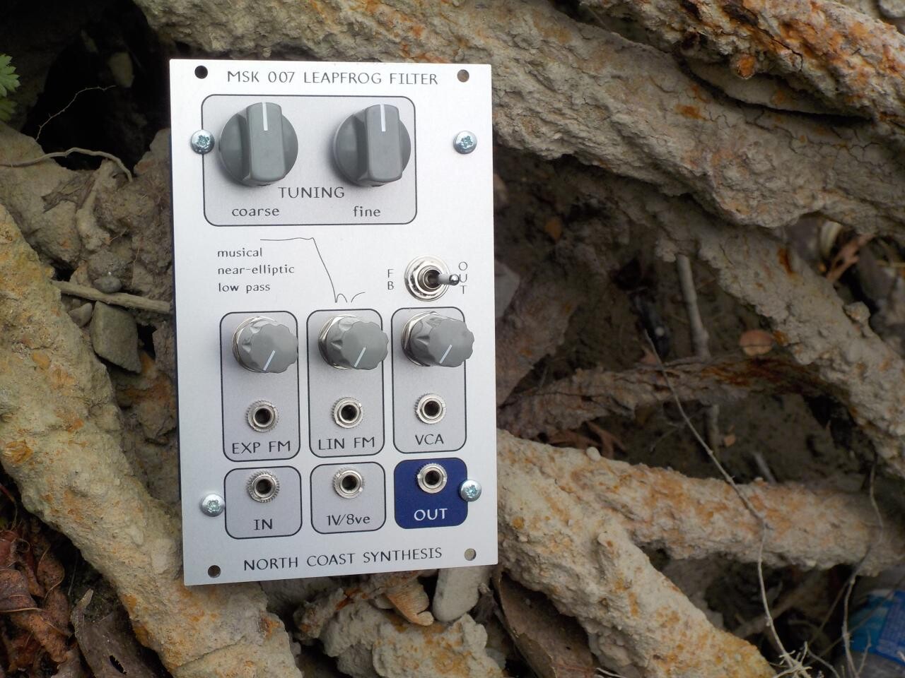
Is that true? Do sharper filters really have more group delay? I thought that instead of just hitting you with more equations and simulation plots, it would be fun to test it by measuring real filters. Looking at my own modular rack, the sharpest low-pass filter I own is a North Coast Leapfrog five-pole filter; and the least sharp is the one-pole output on an Intellijel Dr. Octature II. I tuned them both to oscillate at 1000 Hz with feedback, then turned the feedback down to zero, fed a 250 Hz square wave into both filters, and checked the group delay with my oscilloscope.
Here is the Dr. Octature II's response:

It's evident that the group delay (shown as "FRR" on the scope measurement) of this very shallow filter is about 100µs. You can also note that the signal coming out of the filter is still fairly sharp-cornered. One-pole filtering, with the cutoff considerably above the fundamental of the square wave, doesn't really take much out of the signal at all.
Now, here's the Leapfrog response to the same square wave:

Where the one-pole filter delayed the signal about 100µs, the five-pole filter delays it nearly five times as much, approximately 500µs. And the shape of the waveform coming out of the Leapfrog is much more rounded, highlighting the duality of time and frequency: sharp cutoffs in the frequency domain correspond to rounded shapes in the time/amplitude domain, with more sharpness in one necessarily meaning less in the other.
I'd like to emphasize that the group delay measured here is just a consequence of the fact that filters are filters. Group delay is part of what it means for a module to be a filter; it is not a defect of the specific filter modules I am testing here, and it cannot be eliminated without eliminating their filtering action. Someone who claims to have a filter or frequency-processing device without "latency," whether by the use of "analog" technology or by some other means, is selling snake oil. (Note that both the Octature and the Leapfrog are entirely analog modules.) Any filters with similar frequency characteristics will necessarily exhibit similar amounts of group delay, although the exact amounts depend on details which are beyond the scope of this article.
The Uncertainty Principle
I've talked about envelopes, frequency shifters, and filters. These are three seemingly different things, but they all involve frequencies and times and they all involve a connection between frequencies and times, where improving the accuracy in frequency seems to hurt the accuracy in time or amplitude, and vice versa. It feels like there's something important going on in each of these things, and it feels like it's the same important thing going on in all of them.
In fact, that's exactly right. The important thing going on here is called the Gabor limit. It is a deep fact in mathematics that when you have a Fourier-transform kind of relationship between two things, concentrating one of them causes the other to spread out. Condensing it down to a single expression is tricky because there are several relevant theorems each covering limited cases and all interconnected with each other, but here's one nice-looking inequality snagged from the Wikipedia article:

That says the uncertainty in time (measured by σt) and in frequency (measured by σf), cannot both be small. Their product has got to be bigger than a specific constant. Shrinking one increases the minimum possible value of the other. It's a highly general result applicable in many different places in a modular synthesizer: wherever you deal precisely with frequencies you lose some accuracy in time, and vice versa.
You may have recognized the title of this section already, and if not I'll make it clearer by mentioning that the Gabor limit is also sometimes called the Heisenberg-Gabor limit. Remember the famous Heisenberg Uncertainty Principle from quantum physics? It's actually the same thing!
Particles in quantum mechanics are thought of in terms of their "wave functions," which are localized blobs of sine-wave stuff roughly similar to the wavelets I mentioned in the section on fast envelopes. There are important differences, including that wave functions are complex-valued and have more dimensions than just time; but there are enough important similarities that some of the same math applies. The wavelength, or frequency, of a wave function is related to the momentum of the particle. But the particle's location, which is like the time dimension in our synthesizer signals, is related to the wave function by a Fourier transform kind of relation. When you know one accurately, you cannot know the other accurately. Knowing a particle's momentum limits your ability to know its position, in just the same way and for essentially the same reason that knowing a sound's frequency limits your ability to know or control its envelope.
So the next time you hear someone complain about a clicking envelope, you can tell them it's happening, and must necessarily happen, because of the laws of quantum physics - and, in a twisted way, you'll be right.
◀ PREV Transistor Mixer press release || Modular synthesis intro, part 11: Digital oscillators NEXT ▶