Modular synthesis intro, part 6: Voltage Controlled Amplifiers
2018-02-04 intro
This is Part 6 in a series that started with Part 1.
When people think of their favourite modules, the humble VCA (Voltage Controlled Amplifier) is seldom at the top of the list. But among experienced modular users it's understood that even if they don't get top billing, VCAs are absolutely essential to having a usable system. The saying is that "You can never have too many VCAs!", and in this installment I look at the different kinds of VCAs and why they're so useful.
What is a VCA?
A VCA is a device that lets one voltage control the level of another. Maybe the most classic example of VCA usage would be to apply an amplitude envelope to a signal, as in the sample patch from Part 1 of this intro series. (Click for larger view.)

Here the leftmost of the two MSK 012 envelope generators has its output patched into the control input of the VCA built into the Leapfrog filter at right. The "signal" input of the VCA is internally connected to the filter output. The rest of the patch (VCO, LFO, and the filter itself) creates a continuous tone. In order to turn it into separate notes with silences in between, it's necessary to turn the signal on and off. The VCA does that, under control of the envelope generator, while also shaping the level of the signal. Each note starts with a burst of high volume, then trails off at the end instead of stopping sharply. That is the effect controlled by the envelope generator, but applied by the VCA.
VCAs are also used in less direct ways, such as to control the level of a modulating signal. Maybe you want your notes to have vibrato, but only have it kick in after a delay from the start of the note. You can use other modules to generate a delayed envelope voltage representing the amount of vibrato, and use a VCA to apply that to the LFO signal before it goes into the oscillator's FM input. "Modulate the modulators," as the saying goes. They can even be used as switches to control rhythmic effects like ratcheting. Having plenty of VCA channels available in your synthesizer greatly opens up the patching possibilities.
In principle a VCA only needs signal and control voltage inputs and an output, but many have additional features, possibly including multiple VCAs in a single module (with or without a mixer to combine their outputs); multiple signal inputs mixed before a single VCA; a manual control for scaling (to adjust how much effect the control voltage has); manual offset (to add some extra "bleed" signal to the output regardless of control voltage, or to prevent signal from getting through at all until the control voltage goes above a threshold greater than zero); or a feature to delay the control input to synchronize with the signal's zero crossings (intended to reduce clicking and, ironically, make the output response sound "faster"). A VCA may also be "AC-coupled" (to kill sub-audio frequencies and offsets, good for cleaning up an audio signal) or "DC-coupled" (necessary for it to work with slowly-changing control voltages at the signal input) or it may offer a choice between the two by means of a switch or separate patch points.
Some VCAs are thought to "colour" the sound with a non-flat frequency response, or greater or lesser amounts of distortion. Others are thought to be "clean." Distortion and frequency response can be measured, but "colour" is hard to be sure about because of the difficulty of doing accurate listening tests. It remains important to many customers when choosing which VCA to buy.
Linear VCAs
The easiest to understand type of VCA, and probably the most popular, is the linear VCA. Here, the gain between the input and output is proportional to the value of the (assumed nonnegative) control voltage. A typical linear VCA might hit unity gain at 5V of control input. If the control voltage is 5.0V, the output voltage will match the signal input voltage. With control input of 2.5V, the output voltage will be half the input. With zero control input, the output will also be zero ("closed"). Later in this article I discuss negative and above-unity-gain control inputs.
For many purposes, linear response to control input is what you want from a VCA. People usually want to control the shape of an envelope at the envelope generator instead of having the VCA itself also apply a nonlinear curve. Linear response may also make it easier to calculate the voltages, if that's something you do.
Popular linear VCAs include the Doepfer A-130 (US$90, multi-input single channel) and A-132-1 (US$80, two basic linear VCAs without knobs); the Pittsburgh Dual VCA (US$159); and the Intellijel Linix (US$329, six VCAs with mixer in one module). There are many others on the market.
Exponential VCAs
Another type of VCA has the gain from signal input to signal output determined by an exponential function of the control voltage. It might be so many decibels per volt. A big part of the reason for this comes down to the fact that human beings have logarithmic ears. If you double the power level of a signal, it sounds a certain amount louder (about 3dB). If you double the power again, it sounds the same amount louder, another 3dB, even though this time significantly more power has been added. (Something similar applies to pitch perception, and to human senses in general beyond hearing.)
Logarithmic ears are pretty much necessary for human hearing to be useful: we need to be able to hear both whispers and shouts, and differences in volume in both ranges, despite the huge physical differences in power level between loud and soft sounds. But one of the consequences of having logarithmic ears is that if you turn a linear knob connected to the control voltage input of a linear VCA, you will find that your perception of how loud the output sounds will increase rapidly in the first few degrees of rotation, then level off about halfway through the knob travel, and there will be little difference in loudness from there the high end. Linear variation of power level does not sound linear or natural to human beings. High levels are much easier to control with a linear knob than low levels; it is nearly impossible to set such a knob to an accurate but very low level.
For knobs as such, we have the solution of "audio taper" potentiometers, which approximate an exponential curve in the relation of knob position to output voltage. Exponential VCAs apply a similar correction at the level of the response to control voltage input. They can be useful when it's important to maintain a smooth change in perceived volume level, for instance from a slow triangle LFO or ADSR envelope, as a signal is brought into or out of a mix. They also create a different shape of transient when used with a fast envelope, which may be good for achieving some special effects.
Because exp() is a strictly positive function, an exponential VCA theoretically never quite closes. If the response is 12dB (a factor of 4 in voltage) per volt of control input, and at 5V control input the output level gives 4V of output, then at 4V of control input the output will be 1V, at 3V of control input the output will be 0.25V, and so on all the way down. Bearing in mind human logarithmic perception, the output level of about 4mV at 0V control input may really still be quite audible, even if is seems numerically much smaller than 4V. Exponential VCAs usually will accept negative control voltages and allow shrinking the output even further until it is lost in the noise floor.
Some examples of exponential VCAs include the Doepfer A-131 single (US$95) and A-132-4 quad (US$150) and my own MSK 006 (plans-only DIY).
It's not necessary for a VCA to have only linear or only exponential response to control voltage. Some offer a control for the response curve, which might be a switch for choosing one or the other, a knob that allows choosing a curve interpolated somewhere in between the strictly linear and exponential response curves, or even a control voltage. This kind of feature is nice if you do want to fine-tune your envelope shapes at the VCA instead of at the envelope generator. Modules supporting it include the Intellijel µVCA II (US$155) and Doepfer A-132-3 (US$140).
Four-quadrant multipliers
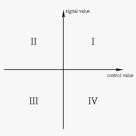
Modules that are called "VCAs" usually amplify a signal value which can be positive or negative, according to a control value that can only usefully be positive. They operate in quadrants I and IV of this diagram (which shows the traditional quadrant numbering used by mathematicians), and so these modules are sometimes called "two-quadrant multipliers."
I have written "value" instead of "voltage" here because it may not be exactly the input control voltage that is multiplied by the input signal voltage. With linear VCAs and no offset in play, a positive control voltage gives positive voltage gain; zero control gives zero voltage gain ("closed"); and negative control voltages are just chopped off, usually treated the same as zero. Exponential VCAs still have nonzero gain at zero control voltage. Negative control voltages are useful but they go to decrease the gain further, in principle never quite to zero.
Exponential VCAs are limited to quadrants I and IV by their nature; it is not possible to put in a control voltage that would correspond to negative voltage gain because all possible control voltages correspond to different amounts of positive gain. But although linear VCAs are usually limited to two quadrants also, we could imagine a linear VCA that processes positive control voltages normally, also accepts negative control voltages, and uses them to activate negative voltage gain. On a negative control input the output signal has opposite phase to the input signal, and gets stronger as the negative control voltage goes more negative. An amplifier like that would be a four-quadrant multiplier: different combinations of signal and control input can take it into all four quadrants.
Examples of four-quadrant multiplier modules include the Doepfer A-114 and A-133 (each US$100), Mutable Instruments Blinds (US$200), and my own MSK 003 (plans-only DIY). The term "ring modulator" is often used to describe four-quadrant VCAs; more on that later.
If you have a control voltage that never goes negative anyway, then a clean four-quadrant multiplier is just like a regular two-quadrant linear VCA and can be used wherever you would use one of those. But four-quadrant multipliers are seldom used that way, not least because they usually cost more than two-quadrant linear VCAs. Instead, four-quadrant multipliers tend to be used with audio signals at both inputs, to create complex timbre effects.
Readers who took and still remember high school trigonometry may know the multiplication formula for cosines. I'm using cosines here to avoid having to discuss phase effects in much detail, but something similar can also be written involving sines.
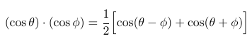
The function cos ft describes a sine wave of frequency proportional to f, where t represents time. If we let θ and ϕ be two different multiples of t, then this equation says that multiplying two sine-wave voltages of different frequencies creates an output that is a scaled sum of two other sine waves, whose frequencies are the sum and difference of the frequencies on the input. Put in 440Hz and 20Hz, get out 420Hz and 460Hz. Multiplying voltages has the effect of adding and subtracting frequencies.
Real signals may be more complicated than single sine waves, but by Fourier theory signals can always be regarded as sums of sine-wave partials. Then for every combination of a sine-wave partial from one input of the multiplier and a sine-wave partial from the other input, we get two partials in the output at the sum and difference frequencies. These partials add up to create a complicated output signal with many partials, even from relatively simple inputs with few partials. Moreover, the partials in the multiplier output are often inharmonic - they are not all multiples of a single fundamental tone. The ability to produce inharmonic partials greatly expands the sonic palette.
And that is how people usually use four-quadrant multipliers in patching: combining two relatively simple, likely harmonic, inputs to produce a more complex timbre. Timbres achieved from this kind of effect are often described as metallic or bell-like. Four-quadrant multiplication is a mainstay of the West Coast style of modular synthesis. One of the quintessential West Coast modules is a combination of two VCOs, a four-quadrant multiplier, and usually a few other modulation or sync features, all put behind a single faceplate and called a complex oscillator. Four-quadrant multiplication also sees use in East Coast-style patches, most often by simply patching two oscillators into the four-quadrant VCA and then using its output as a harmonic-rich source for filtering, where a simpler patch would use a single oscillator.
The sound of the output depends not only on the input signals, but also on how clean or accurate the multiplication function really is. I have been describing it as if the output were really, exactly, a scaled product of the input voltages. Many modules aim to achieve clean multiplication, and it is the only kind of operation for which the sine-multiplication formula strictly describes the output spectrum. Clean multiplication is also something of a necessity for some of the more technical uses of four-quadrant multiplication, such as inside the Bode frequency shifter. But it is also possible for a four-quadrant multiplier to be less accurate by accident or by design, with output not exactly described by simple voltage multiplication, and that is the subject of the next section.
Ring modulators
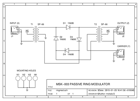
One of the technologically simplest ways to build a four-quadrant multiplier involves a ring of four diodes, often flanked by transformers. My own MSK 003 (plans-only DIY) is a typical example. Note the diodes point nose-to-tail all the way around the ring. This is not a diode-bridge full-wave rectifier as seen in power supplies.
A diode ring like this, with its support circuitry, is called a ring modulator, and properly speaking, it is the only thing that should be called a ring modulator. Four-quadrant multipliers based on other circuit topologies are not ring modulators! Nonetheless, in modular synthesis the term "ring modulator" is usually applied to all four-quadrant multipliers regardless of their construction. You will find four-quadrant multipliers of all types filed in the "ring modulator" category on Modulargrid, and any audio effect achieved by any sort of four-quadrant multiplication is likely to be called a "ring modulation" effect.
Ring modulators originated in radio electronics, where they are often also called doubly-balanced mixers (DBMs), with the confusing radio usage of "mixer" to refer to a voltage multiplier. In audio, a mixer is nearly always a voltage adder of some sort.
The thing about a true ring modulator is that it does not do very accurate four-quadrant multiplication. In order for the circuit to work at all, it is necessary to boost at least one of the inputs to a high enough power level that it effectively induces clipping. That, and other mechanisms by which the diodes do not multiply accurately, usually means there will be a lot of extra partials in the output. As well as the sum and difference frequency for each pair of input partials, true ring modulators tend to also create sums and differences of multiples of the input frequencies (like maybe twice one input frequency minus three times another); sums and differences between frequencies in a single input instead of only across the two; and bleed-through of frequencies from either input directly into the output. And these effects may vary a lot depending on the input power levels and even (because of sensitivity to component variations) among different individual modules built to the same circuit design. Overall, the output of a true ring modulator tends to sound more distorted and dirty than the output of a clean four-quadrant multiplier.
For many users, that's considered an important advantage of true ring modulators.
Amplifier or attenuator?
Some VCAs are limited to at most unity voltage gain. The output voltage varies, depending on the control input, between zero and the input voltage, but the output never exceeds the input voltage. In principle a VCA could be built to allow more than unity gain, and some are (especially those with exponential response), but many others stop at unity. For this reason, there is a popular misconception that VCA should really stand for Voltage Controlled Attenuator. If the voltage doesn't increase, some say there is no "amplification" happening so it shouldn't be called an "amplifier."
To understand why Voltage Controlled Amplifier is the correct and standard expansion of VCA, it's necessary to consider some factors that in modular synthesis we usually try to ignore. Signals in a synthesizer are usually described in terms of voltage alone, but really, any time a signal travels from an output to an input there are three important quantities: the voltage, the current, and the impedance. Properly describing a signal requires two of these three; then the third is mathematically determined. For example, if we know the voltage and the current, the impedance is just the ratio, voltage divided by current. It is also possible for the natural or characteristic impedances of the input and output on a connection to differ, with important consequences for how much power is actually delivered from the output to the input. (The actual ratio of voltage and current on the cable is determined by the input impedance, at least as long as the input is well-modelled by a simple linear impedance; the output impedance affects the overall magnitude of the signal given that ratio.)
Connections can be designed in different ways with respect to impedance, to serve different goals. In radio, it's common to choose a single relatively low impedance (50Ω is one popular choice) and aim for the input and output to both run at that value. Matching the input to the output has advantages for power transfer and preventing reflections and standing waves. Some high-quality audio systems use a similar approach (same impedance at both ends) but with a higher chosen impedance, such as 600Ω. Impedance also becomes very important when transmitting a signal over a long wire, as in telephone and television cable systems. The wire itself can have a characteristic impedance level, and people may try to have the input, the output, and the wire all match.
But in modular synthesizers and especially in Eurorack, with signals transmitted only over relatively short patch cables, it is usual to create a deliberate impedance mismatch between the input and output. Eurorack inputs are supposed to have a characteristic input impedance of "I dunno, pretty high, like at least 100kΩ" and the outputs are supposed to have impedance of "unspecified, but try to keep it low, maybe like 1kΩ or less." Doing it this way has the consequence that signals will be primarily carried on the cable by voltage, with negligible current that we usually don't bother to measure. Eurorack-style impedances make some aspects of circuit design much easier, and they help cover for the deficiencies of low-quality cables. They make it possible to split signals from one output to several inputs with a "passive multiple," whereas keeping impedances matched while splitting a signal is much more complicated. Also, if only the input or only the output really follows the rules, it will usually still be okay; you can afford to have a few badly-designed or "passive" modules with somewhat nonstandard impedances, and the other modules will compensate by sending more current than usual, or drawing less, more or less automatically. Such situations would be much harder to deal with in a system designed to require matched impedances everywhere.
Now think about a typical well-designed Eurorack VCA set up so that the output has half the voltage of the input. Considering voltage alone, half the voltage corresponds to 6dB attenuation, and if the VCA cannot increase the voltage above its input, then it will never amplify. But voltage is not the only relevant consideration. The VCA has output impedance much less than its input impedance. If it maintains its output voltage at half the input voltage, then the lower impedance at the output means the VCA is at least capable (depending on what it's plugged into) of supplying very much more current at the output than it consumes on the input. There is sub-unity voltage gain, but much more than unity current gain. And voltage multiplied by current, a quantity called power, is greater at the output than the input. Even though it reduces the voltage, the amplifier is providing power gain, and power gain is what makes an amplifier.
Traditional guitar amplifiers work the same way. The input impedance is much higher than the output impedance, the current at the output is much greater than at the input, and in the case of a small amplifier running at relatively low volume, it's quite possible for the output voltage applied to the speaker to be less than the input voltage from the guitar, even though the amplifier is doing plenty of amplifying and delivers much more power to the speaker than the guitar delivers to the amplifier input.
For this reason, VCAs are best called Voltage Controlled Amplifiers even when they reduce the voltage. There is a possible exception when someone builds a "passive" (not really passive, but that's a different rant) level-controlling device with a Vactrol and no power connection. In that circuit, the Vactrol acts as a resistor to dissipate a controllable amount of power from the input. It is impossible for more power to come out the output than came in on the input, so the device cannot amplify but can only attenuate. If you want to call one of those a Voltage Controlled Attenuator, I won't object. (But it could still increase the voltage, despite being an attenuator, by the addition of a transformer...)
Continue to Part 7 of this series.
◀ PREV Live-coding a permutation-based fugue || The Music of the Dwarves NEXT ▶