Modular synthesis intro, part 7: the Moog ladder filter
2018-02-18 intro electronics
This is Part 7 in a series that started with Part 1.
Last installment I talked about VCAs, which are important in analog synthesis because of their versatility. This time around I'm going to discuss a type of module with a more narrow focus: the voltage-controlled filter (VCF). Voltage control is so ubiquitous in modular-synthesizer filters that we normally expect something called just a "filter" to really be a VCF unless it is explicitly described as a fixed filter. Filters in modular synthesis are nearly always used to set the timbre of a sound.
And the filter in a typical subtractive-synthesis patch is terribly important in setting the sound; in most patches, the filter is the main determining factor in what the patch sounds like. It's a common misconception that since the oscillator (which I'll discuss in some future installment) is the original source of the audio, there must be big differences between oscillators and it matters a lot which one you choose. Really, and especially but not only in "East Coast" patching, the filter makes more of a difference. Connoisseurs of analog-synthesis music can listen to a track and pick out the characteristic sound of a particular filter, recognizing bands and styles by their preferred filters. Oscillators impart much less of their own character on the overall sound of the instrument.
It's easy to understand why the filter would be so critical when one looks at the analogy with acoustic instruments. In a violin or similar, sound is generated by the bow dragging across the strings, which creates a vibration with many harmonics similar in profile to the sawtooth wave from a modular-synth oscillator. That vibration is coupled into the wooden body, which absorbs some frequencies much more than others, creating the instrument's timbre. If you have a good violin then you certainly ought to put good strings on it (oscillator) and use a good bow (envelope generator and VCA); but it's the wooden part that really matters. That is the filter.
From an electrical and mathematical perspective, filters produce one or more outputs as functions of the input signal described by differential equations that may be more or less linear. The effect of doing that is usually described in terms of what would happen if you fed the filter a pure sine wave at different frequencies. For instance, here's the response of the North Coast MSK 007 Leapfrog VCF (in its default configuration). The solid magnitude curve shows that for frequencies below the reference point, it basically lets the signal right through, with at most a couple of decibels attenuation. But as the frequency increases past that point, the response drops, and from about twice the reference frequency on up, it attenuates roughly 70dB - killing the signal pretty much completely.
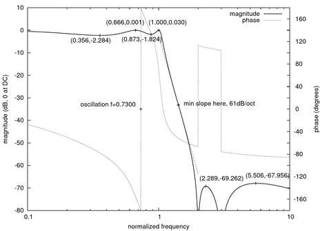
Filters characterized by their frequency response fall into general classes like low-pass (as shown above: it lets through relatively low frequencies but blocks higher ones); high-pass (the opposite); and band-pass (lets through frequencies in some range but blocks both higher and lower frequencies). There are other, more complicated responses possible, and some oddball ones like all-pass, which lets through all frequencies with little or no effect on their amplitude, while instead having useful effects on the phase of the signals.
Although many kinds of filters are occasionally used in modular synthesis, by far the most common is the low-pass filter. That comes about because low-pass filters are what you need to make natural, or most kinds of interestingly unnatural, instrument sounds. Musical timbres are usually rich in low-order harmonics, with the amplitude dropping off rapidly as the frequency increases. That is exactly what comes out of a low-pass filter. To shape the timbre, one can then move the cutoff up and down (changing how many harmonics pass through unmolested before the amplitude starts to drop off); choose a filter with a different shape of cutoff (to control how fast the harmonics do drop off past the cutoff point); or overload the filter or choose one with built-in distortion, to actively create some harmonics and other signal features that may not have existed in the input. It's also a common practice to change the control voltage over the course of a note (with an envelope generator, LFO, or both) to create a timbre that changes over time.
So, keeping in mind that the focus is usually on voltage-controlled low-pass filters in modular synthesis, I'm going to go through another way of classifying them: by the basic form of topology of the circuit. There are only a few popular topologies, and I had it in mind to make this installment of the series cover all of them, but after writing the section on the Moog ladder, I realized it was already as long as I wanted a single posting to be. If I covered the others here in as much detail as I want to, the resulting posting would be gargantuan; so I will leave them for future postings.
The Moog ladder and variations
Robert Moog patented the VCF design that we now call the "Moog ladder" in 1969 ( US Patent 3,475,623) and it's considered a classic. Last time I went looking for a nice image of this circuit diagram, the first several image-search hits were pictures of people with it tattooed permanently onto their bodies. That just goes to show something, I guess. Here's a re-drawn version.
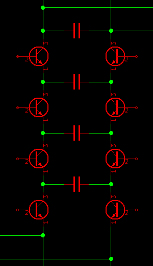
The bases of the transistors are held at fixed voltages that increase from the bottom to the top of the diagram, by a biasing circuit not shown here. Other circuitry imposes a DC current that flows downward through the two chains of transistors. The input is imposed as a differential voltage at the bottom of the diagram, and the output is recovered as a differential voltage at the top - but it's important to understand that in theory, the signal is quite small in comparison to the voltages and currents imposed by the biasing arrangement. This is a basically static arrangement of transistors with fixed voltages and currents, which will be tweaked in minor ways by the signal.
Transistors operated in this way obey an exponential voltage-to-current curve. Any small change in voltage will result in a significant change in current, or vice versa; and for small changes, this effect is nearly linear. Zooming in on a small part of the exponential curve, it looks like a line. But the slope of that line depends where on the curve we look. Changing the relatively large bias current causes the transistor emitters to float to a different voltage, and then the voltage/current relationship with respect to small changes in either, will obey a different ratio.
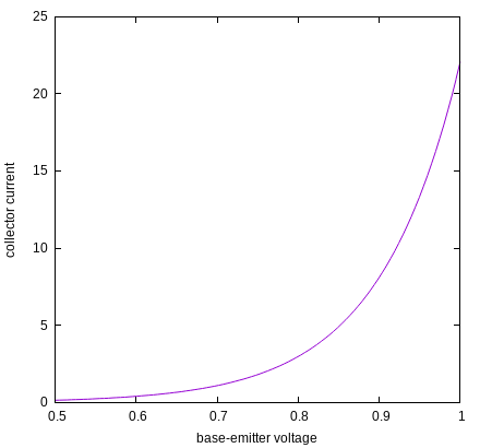
(Curve parameters chosen to make a pretty picture; in a real transistor, if the lower scale is measuring volts, the curvature would be more extreme than what's shown.)
So we have an important voltage-to-current ratio here, and a voltage-to-current ratio is effectively a resistance, hence the title of Moog's patent: Electronic high-pass and low-pass filters employing the base to emitter diode resistance of bipolar transistors. This transistor resistance is variable; it depends on the amount of DC bias current, which shifts the transistors to different parts of their response curve. So the circuit as seen by the AC signal, for small signals, looks like this:
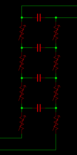
And that is just the circuit of a basic passive RC low-pass filter. The capacitors provide a path for high-frequency signals, causing them to be absorbed before they get to the output, while lower-frequency signals are less inclined to pass through the capacitors and instead go through the resistors, arriving at the output with less attenuation. The frequency boundary between these two kinds of behaviour depends on the values of the resistors, which (because they are not really resistors but biased transistors) depends on the bias current and therefore the control voltage. That's the basic principle of the Moog ladder.
In practice, it's really more complicated than that. There are non-linear effects because the approximation for very small signals may not really apply to signals of the magnitude people actually use. There are ways in which the biasing, signal injection, and signal recovery circuits may not function in the simplified way I've described. All these things contribute to distortion of the signal and alterations of the frequency response, with audible effects on the output. Whether because of familiarity or its intrinsic qualities, many people like the characteristic sound of the Moog ladder filter, and so it remains popular even now that we have other technology that could eliminate its deviations from the theoretical ideal.
During the time the Moog transistor-ladder filter was subject to patent, other manufacturers couldn't use it without licensing it from Moog. (There was a famous lawsuit...) That led to the development of other designs attempting to get the same effect by other means. In particular, it's possible to use strings of diodes, which have their own exponential voltage-current characteristic, instead of the transistors shown above. The resulting filter works in substantially the same way, but since the diodes don't have bases to connect to fixed voltages as the transistors do, it changes some of the underlying math and makes analysis more complicated. Hobbyists, even after the patent expired and the original Moog topology was free for all, have also done some interesting experiments with using more exotic components, such as LEDs.
The Moog ladder is usually built as shown in my diagrams with four capacitors in the core, and (though I deliberately did not write in the capacitor values) all the capacitors the same size and all the transistors more or less matched. Having four makes it a four-pole filter, with a frequency response determined by fourth-order polynomial functions, which in turn means that (in the mathematical limit for high frequencies) the response rolls off at 24dB/octave - not as steep as the near-elliptic filter shown in my Leapfrog diagram earlier, but steeper than the 12dB/octave roll-off typical of two-pole state-variable filters. Using the same size for all the capacitors, in combination with other symmetries in the circuit, gives it (only approximately, in practice) what's called a Butterworth frequency response, with no little extra peaks or ripples. Below the cutoff frequency the response is flat; then at the cutoff frequency it smoothly rolls off into its 24dB/octave slope. Users can add a bit of variety by introducing feedback, which has the effect of increasing the response in a sharp peak near the cutoff frequency. All these factors are part of the characteristic sound of this filter.
In the next installment two weeks from now, I plan to cover state-variable filters, the other major family of VCFs commonly used in modular synthesis.
Continue to Part 8 of this series.
◀ PREV The Music of the Dwarves || A note on RSS NEXT ▶
