Modular synthesis intro, part 8: State-variable filters
2018-03-04 intro electronics
This is Part 8 in a series that started with Part 1.
Voltage-controlled filters (VCFs), as I've said before, are critically important in modular synthesis because more than any other type of module, they define the sound of a synthesizer voice. There's often a misplaced emphasis on oscillators; in analog synthesis and especially traditional "East Coast" subtractive synthesis, the low-pass filter really plays a bigger role. In Part 7 of this series I talked about the Moog transistor ladder, a design of great historical importance which is still relevant today because people just really like its sound. I went into a bit more electronic detail than I usually would in an introductory article, because the electronics of the Moog ladder are important and interesting. This time around I'm going to describe the two-pole "state-variable" design, and again I'll go into some technical detail but maybe with a little more description of the practical aspects for synth users. There will probably be one more installment about filters, covering unusual designs that don't fit well into the "Moog ladder" or "state-variable" categories, before I move on to other intro topics.
State-variable filters are probably the most popular family of synthesizer filter designs today. If you see something just called a "VCF," chances are good that it'll be a two-pole state-variable design. There are several important reasons for that.
- "State-variable" is more properly a method of filter analysis than a specific filter design nor even a design method. It is, properly, how you get from a filter to an understanding of what the filter does; not a way of getting from an idea to a realized filter design nor the realized design itself. As a result, it's very easy for many different designs to be called "state-variable" just because they can be understood that way, whether that is where they originally came from or not. The size of the category then comes partly just from the fact that it has such a broad definition.
- Design guided by state-variable analysis allows almost any VCA to be adapted into a filter. Thus, designers can take any interesting or cheap VCA they have, and turn it into a corresponding VCF product with relatively little development work. That makes it attractive to manufacturers. There are endless possibilities for "vactrol state-variable VCFs," "OTA state-variable VCFs," "SSM2164 state-variable VCFs," and so on, just by swapping in different VCA elements.
- It is easy for a fairly traditional two-pole state-variable design to be adapted to do high-pass, band-pass, and low-pass all in the same module, which is good for marketing because buyers can be told they are getting three filters for the price of one.
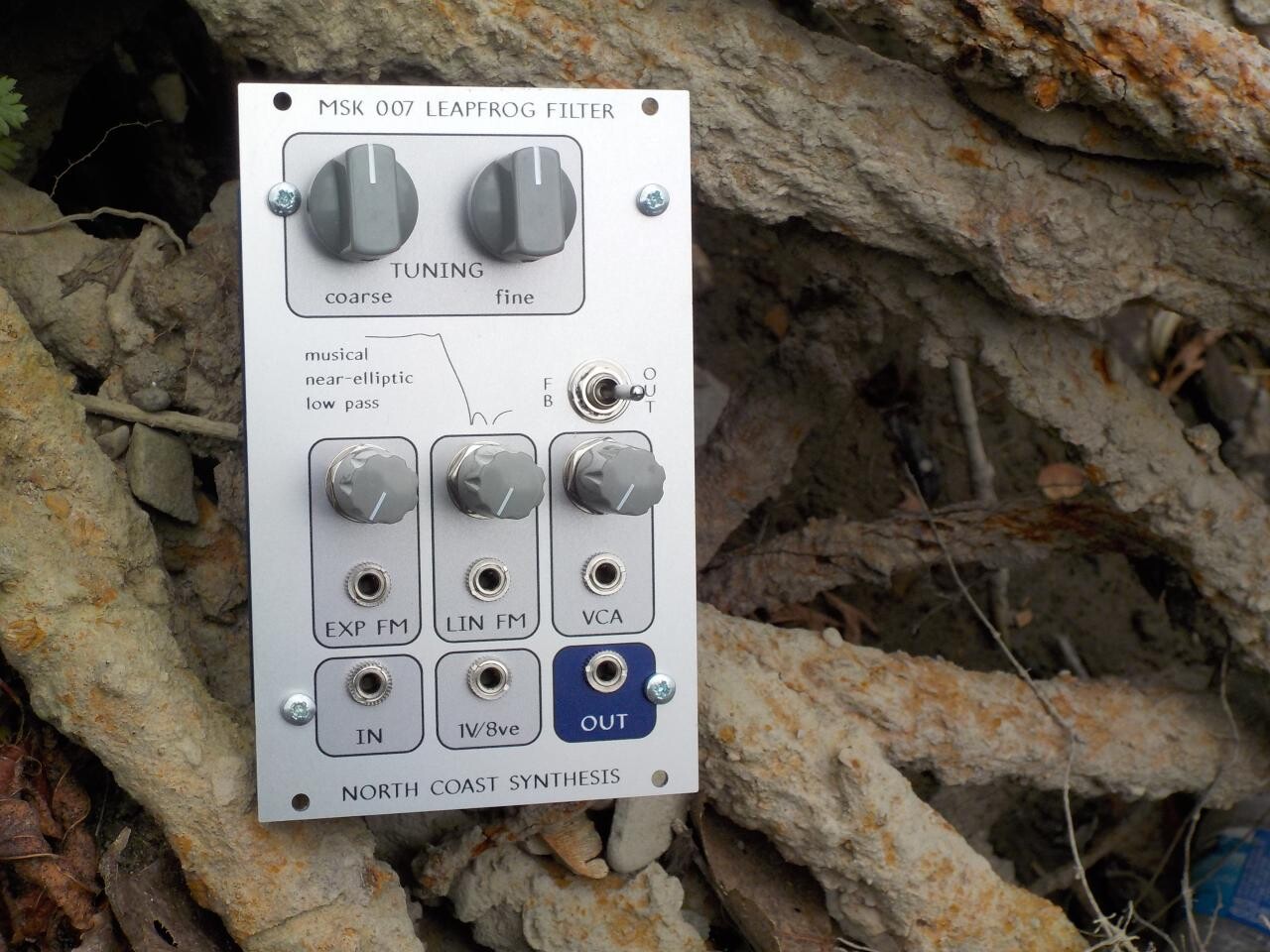
For this article I'm going to use "state-variable" primarily to refer to a more or less classic two-pole design, usually with multiple outputs, in order to avoid making the category so broad as to be meaningless. That excludes things like my own five-pole one-output Leapfrog, even though the Leapfrog actually is based on a state-variable analysis, because it is so different from what people usually mean when they say "state-variable filter."
Examples of fairly traditional state-variable filters include the Intellijel µVCF (US$160); Mutable Ripples (US$200, four-pole design); and Doepfer A-106-5 SEM VCF (US$115). As of October 2018, I'm working on a design of my own for a future North Coast Synthesis two-pole state-variable filter called the Coiler, and have made some videos about my design process.
Two-pole designs always have a 12db/octave low-pass slope in the mathematical limit for high frequencies, and they're usually designed with a Butterworth response curve, which comes from the two filter poles being at the same frequency and has the consequence that the frequency-response behaviour is very smooth, without peaks or notches. However, it's also common for the design to include a controllable amount of feedback (really, a controllable reduction in the default amount of feedback), which creates a single, possibly very sharp, resonant peak near the cutoff frequency. Increase the resonance enough, and the filter will oscillate with a reasonably pure sine waveform.
The usual kind of state-variable filter offers three different outputs, for low-pass, band-pass, and high-pass filtering; they share a single input and cutoff frequency. Some designs leave out one, or do some additional processing to generate another (such as a notch or an all-pass output). However, it is possible to invert the structure of the filter and have separate inputs for the different filter modes all feeding to a single output. The Doepfer A-106-1 Xtreme Filter (US$120) is one example.
How it works
Without going into much, or really any, mathematical detail (you can find that in other sources) I'm going to try to convey some idea of what the "states" and "variables" in a state-variable filter actually refer to.
Suppose you have some kind of device that has an electrical input and output. In very simple cases, you can describe what it does just as a function of the voltages, moment by moment without any reference to changes over time. For example, the North Coast MSK 008 VC Octave switch adds and quantizes voltages in a relatively complicated way, but with no reference to time - the voltage at the output of each channel is just the sum (or difference) of the two CV inputs plus the nearest integer in {-2,-1,0,1,2} to the QUA input. Change an input voltage and the output voltage changes immediately, but for deliberately-introduced limits on frequency response that ensure stability; it basically has no memory of previous values of the inputs and does not depend on the past.
But if you want to build a filter, which responds differently to different frequencies, then you need some way for it to remember voltage values over time and see how fast they are changing. An instantaneous value of 1V on the input could equally well be a DC control voltage (zero frequency) or the peak of a sine wave with a frequency of 500Hz and amplitude of 2V peak to peak. Or, of course, an infinite number of other things. One way to tell the difference between those to is to remember what the voltage was one millisecond earlier - with the sine wave it will have been -1V at that point, half a cycle ago, whereas the DC voltage would have stayed at +1V throughout.
Any filter that actually works must contain some kind of memory of previous input voltages, which might possibly be spread out in a complicated way over many components of the filter. At any moment the filter will be in some state which depends on what happened in the past, and which affects how it responds at the present moment. And the filter's current state can be described by mathematical variables: state variables. The state-variable analysis method concentrates on isolating the state variables, on an abstract level that may or may not correspond to specific physical quantities, and describing the filter's behaviour in relation to the abstraction. And a design guided by the state-variable method will usually connect the state variables directly with specific, explicitly measurable, physical quantities, instead of leaving them implicit. Most often, the state variables end up being equal to the voltages across specific capacitors.
If you want to build an analog circuit with a memory of previous voltages and behaviour that is easy to describe mathematically, one of the easiest ways to do it is to build an integrator. The output voltage of the integrator (which is usually tied to the voltage across one capacitor within the integrator circuit) is like a running total of the input voltages. At any given moment the output voltage increases or decreases at a rate determined by the input, so that the output represents a memory of everything ever seen at the input.
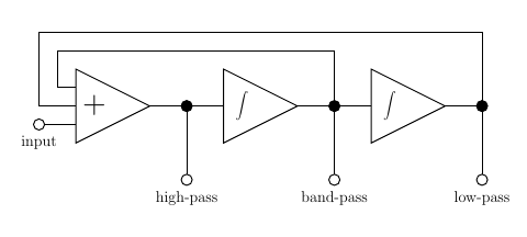
When you start trying to connect state-variable analysis with filter design, it falls out of the analysis that you might typically want to have two state variables, and it's convenient to define them in terms of integration. One useful output from the filter is a weighted sum of the two state variables and the input; one state variable is the integral of that; and the second state variable is the integral of the first one. Expressing those mathematical relationships as a block diagram gives something like the following.

There are other possible ways to organize the blocks, in terms of where you inject the input and what outputs you get. What I've shown as an "adder" on the diagram may really subtract one or more of its inputs; it is intended to represent the more general math concept of a "linear combination" of the inputs, some of the coefficients of which might be negative. But the basic concept is very simple and general: you have integrators (denoted by ∫ in my diagram), which remember the state variables, and usually some sort of feedback and summation network among them. In this case, it's set up so that each of the state variables also happens to be a useful signal in itself. The high-pass signal is calculated from the input and the state variables by a weighted summing amplifier ("+") and it also happens to be the value we need as input to the integrators that will calculate the state variables.
An integrator has a time constant, which expresses the answer to the question "When the input is one volt, at how many volts per second does the output increase?" If you were paying close attention, you'll have noticed that the time constant of the integrators is the only way in which time enters into this circuit topology at all. Everything else is just routing and summing instantaneous voltages, with what is supposed to be a flat wideband frequency response. So if you scale the time constant uniformly, for instance by inserting a VCA upstream of each integrator (or designing the integrators to be voltage-controlled in the first place), then you are scaling the entire behaviour of the filter in time and thus in frequency. That shifts the cutoff frequencies of the filter outputs proportionally up and down while ideally affecting nothing else.
Swap in your favourite integrator, VCA, and summing amplifier designs; maybe play a bit with rearranging the inputs and outputs; change the weighting on the feedback paths; and you quickly get an endless variety of VCF designs, all of which work pretty well and can be understood by a single, reasonably simple set of mathematical tools. The MSK 009 Coiler VCF is one of my own designs of this type - it uses conventional LM13700-based VCA elements, with unique inductor-based integrators.
State-variable variant: the Polivoks VCF
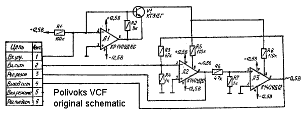
According to Papareil Synth Labs, this is the original Russian schematic for the VCF section of the Polivoks, a classic Soviet synthesizer. At first glance, it looks like a straightforward state-variable design. At second glance, it looks like a joke.

The op amp at upper left, and associated transistor, are not the summing amplifier; they form a voltage-controlled current source whose output is applied to the two other amplifiers through R5 and R8. The summation function is performed instead by a resistor network consisting of R3, R4, and the input circuitry not shown that applies signal from the left. The two integrators generate low-pass and band-pass outputs. All this seems straightforward.
But look at those integrators again... if they even are integrators... where are the capacitors? What's really going on here?
As I said, filters need to have memory, and analog memory usually means capacitors. There are no capacitors in that circuit diagram. The "integrators" seem to be just VCAs, and if they really are just VCAs, this circuit has a flat frequency response and does not function as a filter at all. There must be a trick.
The trick is that the chips used in the Polivoks VCF circuit are a specialized type called "programmable operational amplifiers," cloned by the Soviet military-industrial complex from an American model. You may recall that in my article on op amp stabilization, I mentioned op amps need to roll off high frequencies with a compensation capacitor, and that modern op amps have such capacitors built in although we may sometimes also add external ones. These Soviet programmable op amps have such built-in capacitors, and they are being used as the integrator capacitors here. The "programmable" aspect means that the chips also accept a control current and function to some extent as VCAs. So - although doing it at audio frequencies requires pushing the programmable op amp chips somewhat out of their intended operating envelope - these chips provide controllable integration in a single chip with no visible capacitors! The Polivoks VCF, then, is just a more or less straightforward state-variable VCF built using programmable op amp chips as combined VCA/integrator blocks. Those chips are today somewhat exotic, but for civilians in 1980s Soviet Russia, they were some of the easiest chips to obtain, because they were available as military surplus.
The behaviour of the programmable op amp voltage-controlled integrators in the Polivoks VCF circuit is far from the mathematical ideal, but it's still close enough that the filter does function as a voltage-controlled low-pass or band-pass filter. And those imperfections give it a unique sound that many people find appealing. I myself fell in love with it on hearing a demo of the Erica Polivoks VCF (now seemingly discontinued in the version I bought, but they offer a successor for about US$200 assembled, and various related DIY kits). From my point of view this filter design gives a very "organic" sound that resembles an acoustic instrument or a voice. The Harvestman also produces a highly-regarded Polivoks-style VCF.
State-variable variant: the Wasp VCF
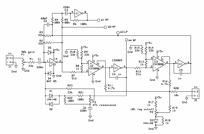
The EDP Wasp was a cult-classic synthesizer from the late 1970s, best known today for an unusual VCF section which looked something like the following. Circuit diagram from Fonitronik's posting of the Jürgen Haible design for a Wasp VCF clone (full schematic is in the PDF file labelled "PCB" on that site).

It's easy to recognize the CA3080 chips as VCAs; and it's easy to line this diagram up with my block diagram of a basic state-variable VCF with a summing amplifier at the left and two voltage-controlled integrators, producing HP, BP, and LP outputs. There are clearly visible integrator capacitors C4 and C5, so nothing like the shennanigans of the Polivoks is going on here. Except.... where are the op amps?
Those CD4069 chips are digital CMOS inverter chips, which it would seem have no place in an analog audio filter at all. The trick this time is that when standard analog op amps are used to build integrators and summing amps in a more traditional filter circuit, the op amps are usually used with the positive input grounded and stuff attached to create a feedback loop around to the negative input. In that configuration, what the op amp actually does is very simple: it is an inverting voltage amplifier with very large negative gain and no particular requirement for linearity. And except for some DC biasing issues that's just the same thing a digital inverter is. The output stage of a CD4069 looks a lot like the output stage of a modern CMOS analog op amp. So instead of an op amp, we could swap in one of the units of a CD4069, pretend it really is an op amp, and the result will be at least sort of like the result of using a proper op amp.
Back in The Day, it was cheaper to buy a CD4069 and have six op-amp equivalents in a single package than to buy a (probably more expensive) chip with at most four real op amps, so this trick of abusing digital logic for analog purposes was actually fairly common. Much like the Polivoks trick of using programmable op amps to avoid capacitors and separate VCAs, the original inspiration for the circuit probably came from saving money, but the consequences of doing that led to a circuit with a unique sound that people came to value on its own merits.
Doepfer's A-124 Wasp VCF (US$110) is considered a classic, and is often recommended to beginners as a low-priced and good-sounding multimode filter for small systems; though it also has a reputation for destroying its CD4069 chip by operating the chip outside of specification. It's common advice to buy a dozen or so spare CD4069s when you buy an A-124 (the chips come about two for a dollar) and just replace them whenever they blow out.
I've summarized the basic state-variable filter and how it works, and described a couple of unusual variations worth knowing about. My plan in the next installment of this intro series is to describe a few more unusual filter types that aren't well classified as Moog ladders nor as classic state-variable designs - including my own North Coast Leapfrog - and then in later installments, go into other kinds of modules you might want to have in your system.
Continue to Part 9 of this series.
◀ PREV Voltage control modifications || One minute op amp analysis NEXT ▶
