How to choose component values
2019-07-28 design electronics
When I draw the first draft of a new circuit design, I'll usually work out the topology of the circuit first, and leave out any component values unless it's instantly obvious what they need to be. The topology means which components exist and how they connect to each other, and it's a separate step from deciding their values. I'll come back and fill in the missing values later. There's interaction between these two steps, and I may well modify the topology in later drafts of the schematic as the requirements become clearer, but there's still a definite progression from working on the topology to specifying the component values.
この記事は 日本語に翻訳されています。<リンク>Ken Sendaさん(ツイッターで@Ken_Senda)ありがとうございます。
Beginning designers often wonder just how to do that step of choosing component values. Textbooks and design resources on the Net often go into specific facets of the problem without looking at the big picture; and example designs usually don't explain where the component values came from at all. In this posting I'll go through some of the different techniques people find useful for this problem in general.
As a quick example, look at this simple op amp circuit which might be the control voltage input of a synthesizer module.

There are different ways to think of it, but I usually think of component value selection as a constrained optimization problem. For each component, there are certain hard limits on what the value could possibly be. For instance, each component has to have a value we can actually obtain; there's not much use drawing a circuit that calls for a 10-farad capacitor if we can't actually buy or build one of those. There can be limits imposed by the component ratings themselves: for instance, the power dissipated in a resistor or the voltage across a capacitor must not exceed the maximum rated limits of the components we're going to use. These are constraints on component selection - rules that limit which choices among the universe of imaginable components, we could actually make. Constraints are potentially complicated and may interact among different components: for instance, we may need two resistors to be in a specific ratio to each other, which could be realized by many different values for one as long as the other has the right value implied by the choice of the first.
But there may still be many choices possible within the constraints, and much of the art of circuit design comes down to choosing the best component values among the possibilities that would basically work. Choosing the best values is the optimization part of the constrained optimization problem. For instance, we may want to choose the cheapest components that will work; the easiest ones to obtain; the ones that look nicest; the most convenient physical sizes; or the components that will produce best results for some measurement that does not have a hard limit on acceptable values, like noise or power consumption.
Values forced by external considerations
Sometimes there's an external requirement on a circuit which constrains a component so much that we don't need to make a decision. In the example circuit, the input impedance is going to be equal to the value of the input resistor R1 because that is a basic fact of how this kind of inverting amplifier works. If we take the Eurorack standard input impedance of 100kΩ as a hard constraint, then that means we're done: R1's value has to be 100kΩ. I would probably write that right on the schematic even at the "topology" stage, as in the figure, because it's known right from the start.
Of course, such a constraint may not be set in stone. It probably wouldn't happen in this particular circuit, but we could imagine that there might be a reason I would want to accept an input impedance that wasn't exactly 100kΩ, in order to support some other goal. Then I might come back and change this 100kΩ value, or even leave it unspecified for the moment, to be chosen later once I have narrowed it down using my other considerations.
Using convenient parts
High-quality panel potentiometers are expensive and difficult to source. In a commercial manufacturing situation it's undesirable to tie up a lot of money in an inventory of many different kinds. The same is true for hobbyists; everybody would prefer to have only a couple of standard potentiometer types used in everything they build. So if I'm designing a new module that needs a linear panel pot, I'm likely to reach for one of the 100kΩ units I already use in existing modules like the Leapfrog if I think it's a reasonable choice; using a new value not already on my shelf is only justifiable if I'm sure nothing I already keep in inventory can possibly be made to work. For this reason I'd probably make R2 in the example a 100kΩ panel pot.
Often these choices are somewhat arbitrary. A circuit that calls for an NPN discrete transistor often will work fine with any common type; but I'm most likely to specify a 2N3904 or a 2N5088 just because those are the kinds I usually use in other circuits and it's convenient to keep repeating the same ones. Someone with different inventory would probably choose other types.
Sometimes a whole circuit will be designed around a specific part. That's more common at the topology stage of design - if I want to build a 2164 VCA, then it dictates the existence of certain other component types in a certain arrangement - but if the parts I want to use have specific values, then those values are defined by using those parts.
Even without choosing a specific part that fully constrains a component value, there are some numeric values that are generally easier to deal with: the "preferred value" series. It's much easier to buy a 0.47µF capacitor than one rated for exactly 0.50µF, so if I had a circuit that calls for about half a microfarad, and I'm going to have to buy new capacitors for it anyway, I'm likely to choose the 0.47µF unit and maybe correct elsewhere for the fact that it was slightly less than the original target. I don't need to go look at a supplier's catalogue to know that 0.47µF is going to be an easy value to buy; but if there were any doubt, I might go shopping for candidate parts to a few different suppliers and come up with a shortlist of possible values before making a decision.
Calculating a value
Sometimes basic circuit analysis makes it possible to calculate a value. In the example circuit, I have a control voltage input coming in through R1, which might have volt/octave scaling, and a front-panel knob (R2) which controls the same parameter. The resistor R3 has the effect of setting the scale for the knob: a voltage between -12V and +12V, that's a 24V range, is applied to the op amp summing node. What's the right value for R3? If it is large, then the knob will not have much effect; if small, the knob will have a lot of effect.
Maybe I decide that the knob should cover a 10 octave range. This decision might come from my experience of using tuning knobs on other modules. It means the 24V range of the potentiometer output should be equivalent to a 10V range on the control voltage input; so to achieve that, R3 should be 24V/10V = 2.4 times the value of R1, therefore 240kΩ.
It happens that 240kΩ is exactly an E24 preferred value, so it'll be easy to find resistors of that value; and in fact I already have such resistors in inventory for building Leapfrogs (where they are used in a similar application, to set the scale of the coarse tuning knobs). So it's natural to specify a 240kΩ resistor here. If the calculated value were not a preferred value, I might pick the closest. I might also consider using something else only approximately equal to the calculation even if hitting it exactly were possible - for instance, maybe if I already had a bunch of 220kΩ resistors used elsewhere in this design, I would say "220 is close enough to 240" and use that for R3, making the tuning range just a little wider in exchange for avoiding the need to include another line item on the bill of materials.
There can be a need to cross-check the consequences of this kind of calculation even when it seems easy. In this particular example, the combination of R2 and R3, which I've just analysed as a voltage between -12V and +12V in series with a 240kΩ resistor, is not really exactly that. At the ends of the range R3 sets the impedance, so the adjustment-range calculation is correct, but the 100kΩ pot creates an additional impedance that varies from 0Ω at one end, to 25kΩ (the two halves of the track in parallel) at the centre, and then back to 0Ω at the other end. The impedance seen by the op amp for this control input thus varies between 240kΩ and 265kΩ, with the result that the knob position will not really have a linear effect on perceived pitch - it will be more sensitive near the ends and less near the middle.
After looking carefully at that, I'll probably decide that it's not a problem. The knob's effect will be close to linear and doesn't need to be exactly so. But someone doing a different design, for instance with a multiturn pot and a turn-counting knob, might want the pot's effect to be really as exactly linear as possible, and in that case they would need at least a smaller ratio between R2 and R3, and quite possibly to change the whole topology to insert a buffer between the pot and U1A. The take-away here is that even what seems like an easy calculation for the value of a particular component, may not be the whole story.
Signal levels
The resistor R4 sets the gain of the op amp, which determines the scale of the signal coming out. That becomes another variable for the designer to choose - which will probably be related to decisions made in whatever circuit stage consumes the output of this one. To choose R4, I have to look ahead at where the signal is going. The signal is 1V/octave at the module input, and a 100kΩ feedback resistor for U1A would produce that same signal level of 1V/octave (although inverted) at the output. If it's meant to drive something like an exponential converter, it will quite likely need to be knocked down to a lower level like 18mV/octave at some point later. So maybe I might choose 1.8kΩ (possibly temperature-compensated) to reduce the signal level, and then the next stage won't need to attenuate it. But maybe the next stage needs some kind of resistor network on its input anyway, for instance to allow adjustment, so it makes sense to have some attenuation there and a higher signal level here. Most likely, I would split the difference: use some value for R4 in between 100kΩ and 1.8kΩ (perhaps near their geometric mean, which is 13.4kΩ) and then also do some attenuation in the downstream stage.
There could be many considerations going into this decision, including what values of temperature-compensation resistors are convenient and where I want to do the temperature compensation, how big I want the signals to be at op amp inputs to overcome offsets, the range of signal voltages I want to be able to handle without incurring distortion, noise considerations for the use of large resistance values, and so on. But this particular circuit can produce a wide range of different signal levels without these other issues becoming big problems, and if the next stage that consumes the signal is similarly versatile, the signal level and the value of R4 may be more or less arbitrary within a broad range.
Using a ready-made circuit
If the circuit topology came from a pre-existing source, the source may also provide component values or a way to calculate them. For instance, if you're cloning someone else's design you may be able to just copy over the component values when you copy over the topology.
That's fine as long as you're building an exact duplicate. However, if there are any changes in the application it may be necessary to change the component values too; you ought to know why the original designer made those choices and whether those considerations still apply. For instance, when cloning a guitar pedal circuit into a synthesizer module, there may be a lot of resistor values that need to change to account for the different power supply, signal levels, and impedances. We also can't ignore the possibility that the orginal designer did not actually make good choices in the first place; there are a lot of mistakes in published designs, even from professionals who ought to know better.
A good general rule for design is that for every component you should know why it's there, and why it has the value it does. If not, more analysis is necessary!
Some beginning designers are inclined to copy specific details of others' designs without really knowing where those details came from, and that can lead to a cargo cult effect. For instance, the values of op amp stability capacitors in beginner designs often seem to be random, because they are just copied over (maybe through multiple generations) from some original that maybe had a totally different IC, and other values for the other components, so that the original reasons for the copied value are no longer relevant. People get away with doing this because the stabilization capacitors often are not absolutely necessary to include at all, and a wide range of different values will at least do no obvious harm to circuit operation. But it would be better to make the choice in a more principled way: first evaluating whether a capacitor is really needed there, and then having a reason for the specific value beyond just "that's what someone else did and it seemed to work for them."
Sometimes the topology of a circuit will be published along with design equations for it. I used something like that in the Leapfrog VCF ; I found a paper by Yichuang Sun in IEEE Transactions on Circuits and Systems which gave design equations for calculating the time constants of the integrators in a leapfrog filter given a transfer function and different numbers of poles, and then I applied those to get the time constants for use in my module. In that particular case it didn't give component values as such, because I had to do a fair bit more analysis to get from the time constants to the component values needed for my particular integrator design. But the published design equations helped with some of the harder steps in the process. Many sources of design ideas provide instructions for calculating component values that can save the designer a lot of error-prone and difficult analytic work in deriving the equations from scratch.
Computer search
There are mathematical and computer science tools designed for constrained optimization problems in general, and these general tools can be applied to the circuit synthesis problem in particular. There's a fair bit of work involved in identifying all the variables that are relevant to the problem, all the constraints that need to be respected and the objective we're trying to achieve, and then coding these things into a form the software can handle. It usually only makes sense to put in this effort for really tricky design problems that don't lend themselves to hand analysis.
For instance, I used the ECLiPSe-CLP constraint solver to choose resistor and capacitor values for the frequency-determining components in the MSK 010 Fixed Sine Bank because it came down to the following problem:
- Choose eight resistor values and four capacitor values
- All of them are between certain minimum and maximum values representing values I can reasonably source with components that aren't too expensive and are the right physical size to fit on the boards
- All of them are from the relevant preferred value series, again for easy sourcing (fewer choices for the capacitors because of what's available)
- Further choose three separate ways to pair up the resistor and capacitor values, to make three different sets of eight frequencies
- No two of the resulting 24 frequencies closer to each other than a certain percentage
- Given all that, maximize the percentage gap between any two frequencies in any of the three sets of frequencies
There are many billions of ways to choose eight resistor and four capacitor values, but some of them are better than others in terms of reducing duplication among the frequencies we can make up by rearranging the set. So a complete search of the space of different basically-allowable designs is infeasible even with a computer: too many possibilities to look at. The constrained-optimization solver uses a fairly sophisticated algorithm to narrow that huge space down to something that, although still large, can be searched in a few hours of computer time. As a designer, the wins are that I don't have to do the search by hand; I don't have to understand exactly how the software does its job if I just know how to get my constraints into it; and so I end up with a decent solution to the design problem that I probably couldn't have obtained by simpler means.
Trial and error
Instead of trying to be smart about it, sometimes the best way to find a component value is to just build the circuit and try different values for the component in question until one works. When the constraints are complicated and possibly unknown, building the circuit and seeing what it actually does can be more efficient than trying to understand and write down the constraints on a particular component.
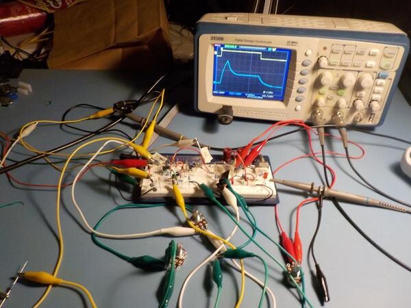
We might "build" the circuit in a simulator like SPICE; really build it, with real components, but on a breadboard instead of a PCB; or go all the way to building a prototype that is as close as possible to the final form of how the circuit will be manufactured including the specific components under consideration, the PCBs, and anything else that might affect the questions we're trying to answer. I use all these techniques at least occasionally for circuit design. Usually it's best to do as little work and incur as little expense as possible - so, software simulation in preference to a breadboard, and breadboard in preference to full prototype - but there will be design questions (such as those involving EMI) that may not really be answerable without at least confirming the previously calculated answers on a full prototype.
Building the circuit has the disadvantage of not directly accounting for variations in components. A simulator will normally simulate components that are exactly the values specified in the design. A test with real components will give results for those specific, individual components. In either case, the components used in production will vary throughout their tolerance ranges, so another instance of the same design built with different individual components may perform differently. Some simulators have features especially meant to address this issue: they can run the simulator repeatedly with different values for the components randomly chosen within their tolerance ranges, and produce statistics of how the circuit performs on average, the extremes observed for different measurements, and so on. If building real-life prototypes, it may be necessary to build several of them to get some idea of how things can vary with component tolerances.
◀ PREV More music of the dwarves || New look for DIY kits NEXT ▶