Middle Path VCO development gallery
2020-02-22 MSK 013 design panels
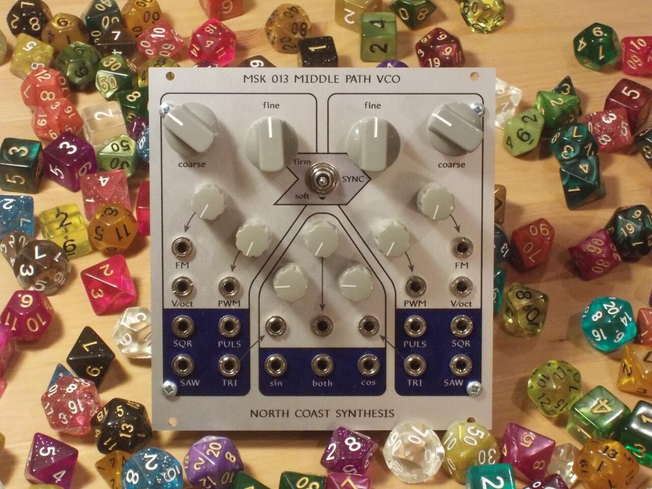
In the last several weeks I've been working on development for my next product, which I'm ready to announce will be called the MSK 013 Middle Path VCO. It's planned to be a "complex" VCO design with two independent triangle cores that can be synced, and a special waveshaping section based on the Barrie Gilbert sine shaper modified to produce quadrature output; that makes it capable of some through-zero phase modulation effects even though the cores themselves are not through-zero. I've been posting pictures from my development process in other places, and this posting gathers some of those together.
I started out with an idea for a sawtooth core that would reset with a constant amount of charge, instead of a constant reset time or resetting to a constant voltage. The big win would be that that eliminates the need to compensate for the reset time when driving the core at high frequencies, so it should improve tracking. It looked pretty good in the simulator. The op amp on the left is a conventional integrator; that on the right is meant to combine the functions of a monostable and a Schmitt trigger, and generate a constant-voltage constant-width reset pulse when the integrator hits its lower voltage limit. This is supposed to happen without saturating the op amp.
I built it up on a solderless breadboard and had a rough time getting it to oscillate at all. It only seemed to stay in oscillation at about 10kHz, and the "sweet spot" on the knob to get it to do that kept moving around. It probably didn't help that I had built the exponential converter with discrete transistors and they weren't in thermal contact; in the final version my plan was (and is) to use a premium THAT Corporation transistor array, which will keep them all at the same temperature and do a lot for thermal stability. But I think the bigger problem was just the unreliability of connections in my breadboard socket - it was good-quality when new, but is now over 30 years old.
It probably also didn't help that I'd built up some capacitor values by putting low-quality ceramic units in parallel, because I didn't have the right values on hand in the polyester type I would use in a more serious build. I'm not even sure what kind of ceramic these discs are, quite possibly Z5U, which isn't good for oscillator service. I like to use up old low-quality and non-RoHS parts in experimental builds like this, partly because I can't sell them and partly because they push the limits of the design. If it works with poor parts then I can hope it will work with better reliability when I put in the good ones, even in the face of tolerance variation, temperature changes, and so on. By the way, you might like to try my Series-Parallel Approximator, which helps calculate ways to make up a desired component value with easy-to-find other values in series and parallel.
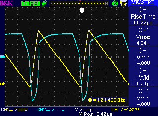
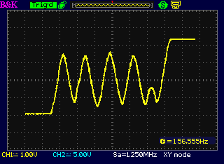
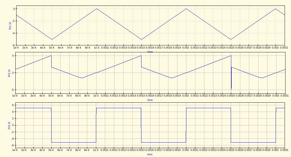
However, I was pleased that when it was oscillating, it produced waveforms that looked a whole lot like the ones I'd been seeing in the simulator. I never used to think very much of circuit simulators, but in recent years they've gotten quite good, if used judiciously.
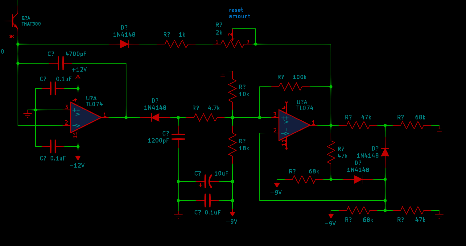
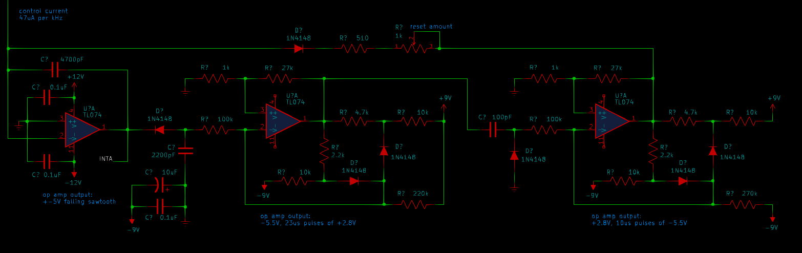
I messed around with it some more and decided that the breadboard socket was causing too many problems - mostly intermittent connections, possibly also issues with stray capacitance - although, honestly, at audio frequencies that shouldn't be a big deal. People do use them well up into the megahertz range. So I resolved to rebuild the circuit on stripboard. But I also decided that trying to collapse so many functions into the second op amp was a problem - the non-saturating Schmitt trigger I'd gotten out of an old TI application note was just too finicky - and so I redesigned the schematic to split that into separate voltage-detecting and pulse-generating stages. Here's the new schematic.
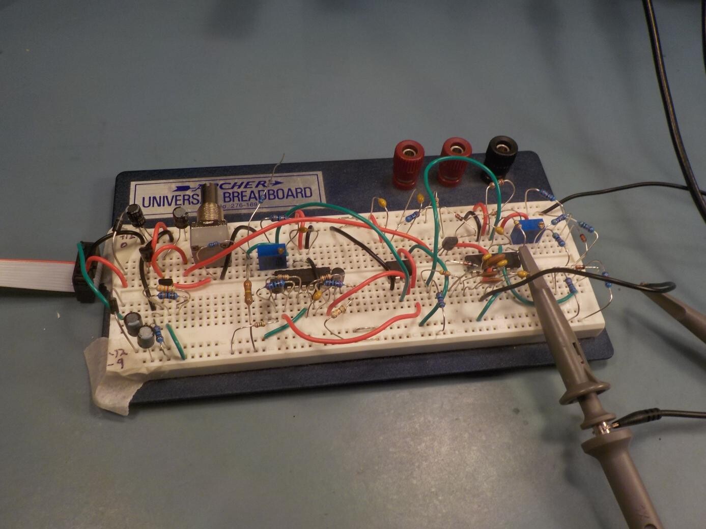
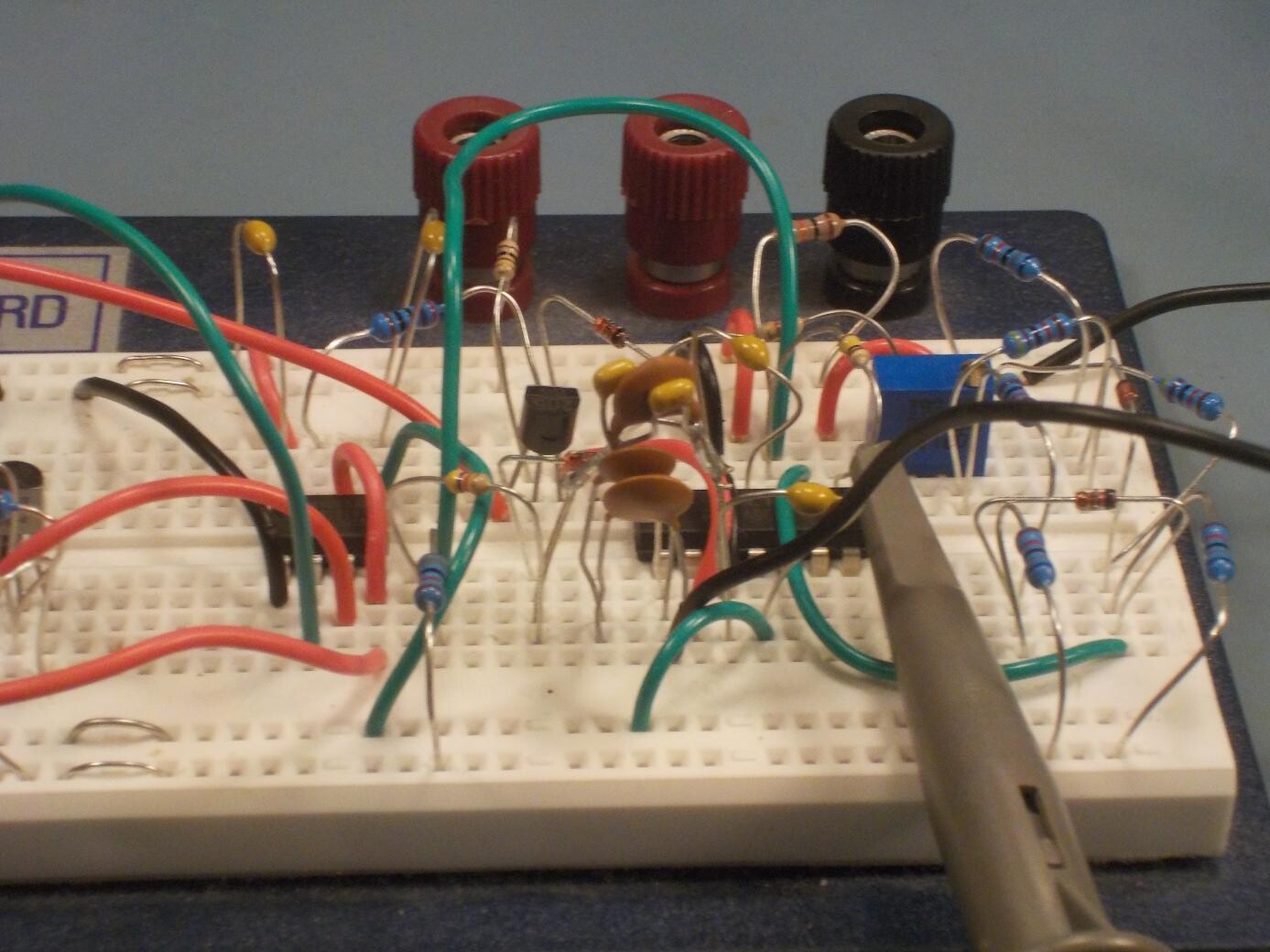
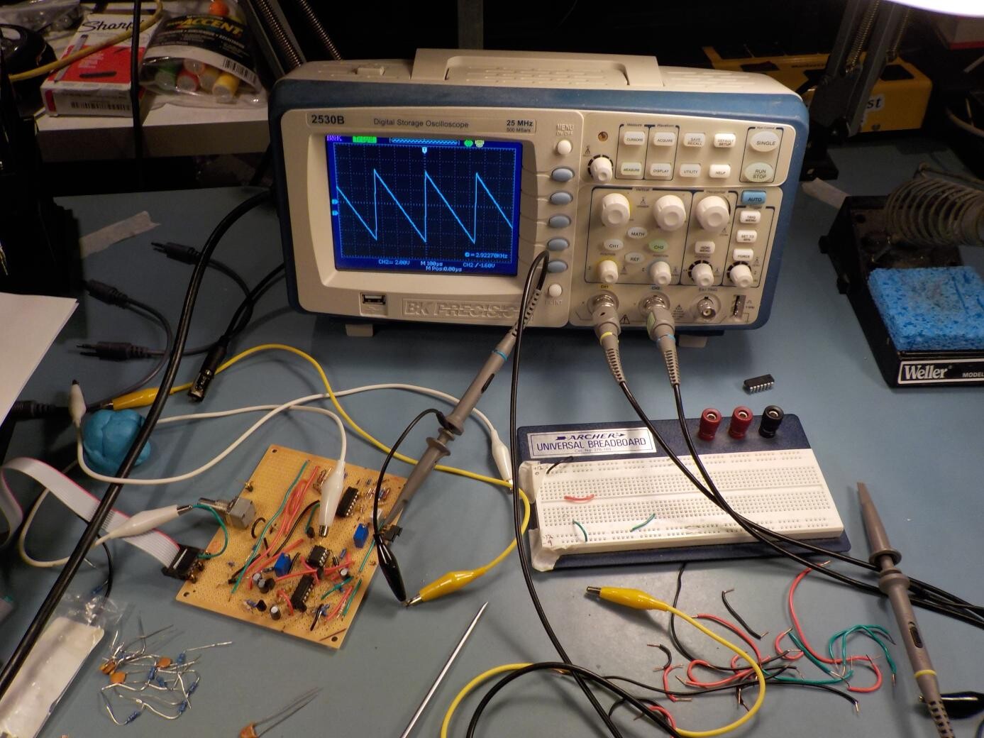
I transferred the new design to stripboard and did a lot of testing.
In so doing I discovered a significant issue which maybe I should have thought of earlier, but it illustrates the limitations that still exist with using a circuit simulator: the constant-charge reset core is structurally vulnerable to locking up. (This may be part of why they aren't popular.) In normal operation, the integrator voltage goes towards its limit, then it hits a specific voltage and the reset circuit is supposed to detect that and send a reset pulse which bumps the integrator away from the limit. (More information on the general operation of a sawtooth core in this archived article). What happens if it misses its reset pulse somehow? The reset circuit is driven by crossing the target voltage, not by the state of being past the target voltage - so it only has one shot at sending the reset pulse. That's important for the constant-charge aspect to work; it can't just keep trying to reset the integrator because then it'll be subject to the unpredictable amount of time that the reset process actually takes. So in case of a missed pulse, the integrator will just keep sailing past the target until it hits the limit set by the power supply, and it'll stay there. That's what I saw happening in my stripboard version: if anything disturbed the oscillation, it would miss a reset pulse and get stuck at the negative power rail.
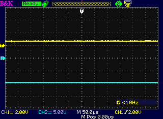
This is a structural issue with constant-charge reset sawtooth cores: unlike cores that reset on integrator voltage level, the core that depends on crossing a level can get stuck if it's disturbed. I could imagine adding further circuits to detect such a state and try to get it back on track with a harder kind of reset, but the whole thing was getting too complicated and I decided to abandon the constant-charge idea and look at a different kind of core instead. That ended up being a triangle core based on LM13700 OTA chips, which might fit better into where I want this module to be, musically, anyway.
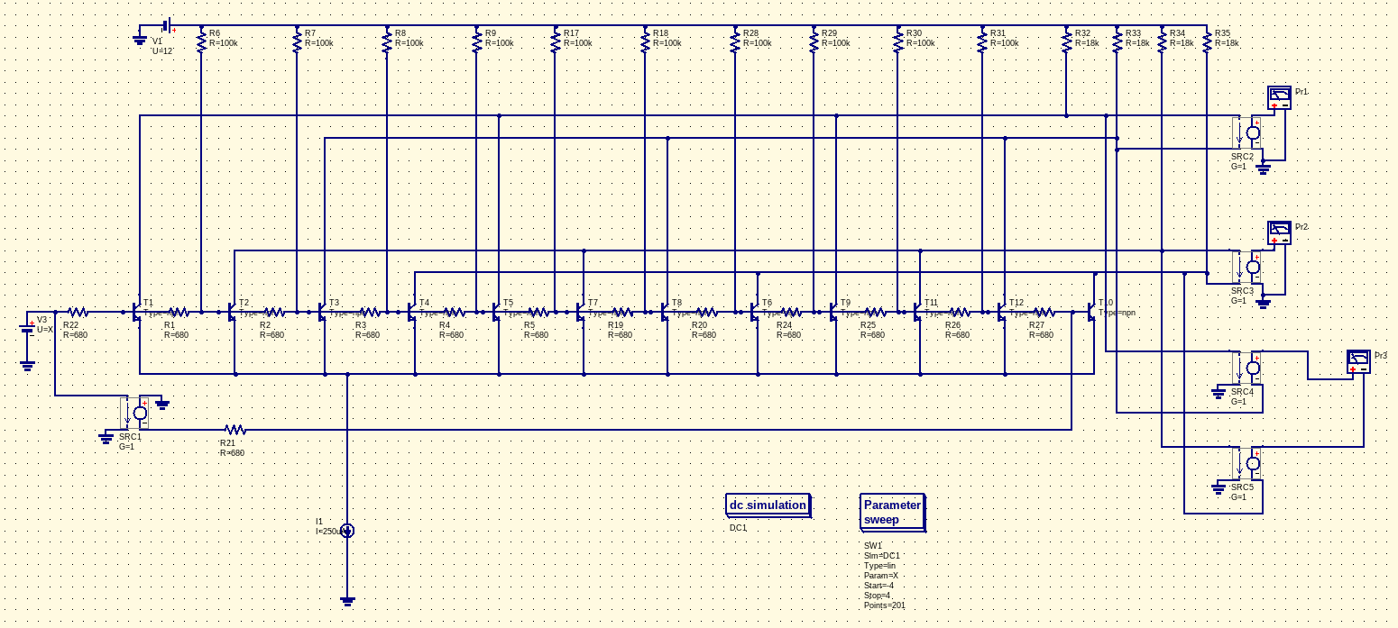
But before looking at that, let's talk about the sine shaper. I wanted to build a shaper based on the Barrie Gilbert design, which allows generating through-zero phase modulation effects without needing to run the oscillator cores backwards. I thought that would be a neat thing to have in a complex VCO, and I had the idea of tapping off signals from different combinations of transistors to generate quadrature signals. Among other things, that would allow generating some kind of stereo image from the module, which I know is something people often think they want in Eurorack. It would also be interesting fodder for a pair of four-quadrant multipliers to generate frequency shift effects. Here's the circuit built up in Qucs; I used dependent voltage sources instead of op amps because the Qucs op amp model tends to be numerically unstable and lock up the simuation.
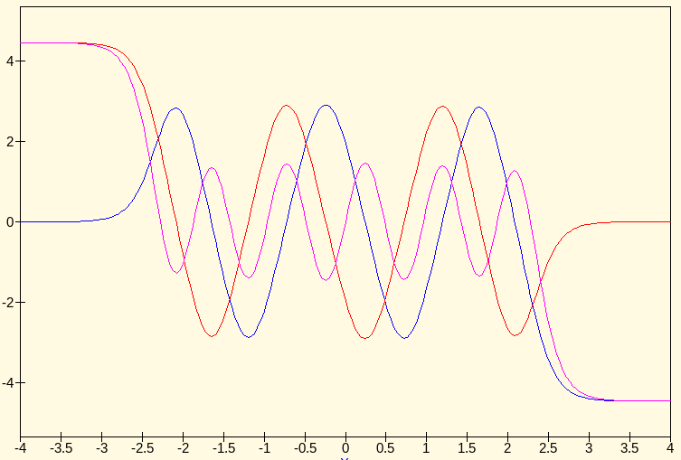
The input-to-output voltage transfer function looked about like I wanted it to.
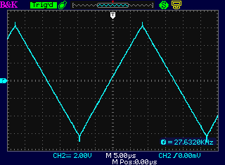
I built the triangle core on stripboard, deciding to skip the solderless socket breadboard stage entirely because it had been so much trouble with the previous two core designs.
This core oscillated reliably all the way from about 5.5mHz (three minutes per cycle - just a little shape distortion caused by leakage currents at this very low rate) up to 27kHz, where a deliberate limit on control current prevented it from going any higher.
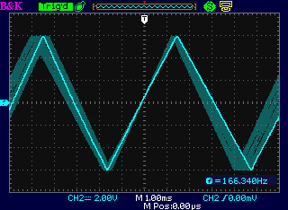
However, there was some weirdness involving varying wave shapes which I tentatively ascribe to thermal effects in the exponential converter (still built of discrete transistors). It has seemed to settle down a bit in subsequent testing.
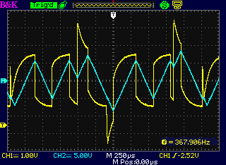
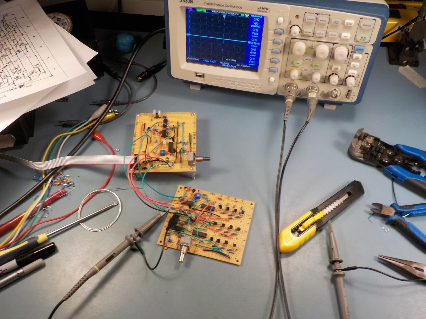
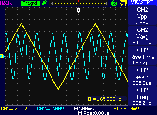
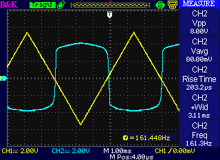
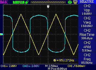
At this stage I was also able to hook the core up to my existing modular synth to try out some of the sync features I had been thinking about. Here's what I call "firm" sync - it's forcing the direction of the triangle core to match the direction of an externally applied asymmetric pulse wave on both edges of the external pulse. It should sound interesting, although even now I haven't actually recorded audio from it yet.
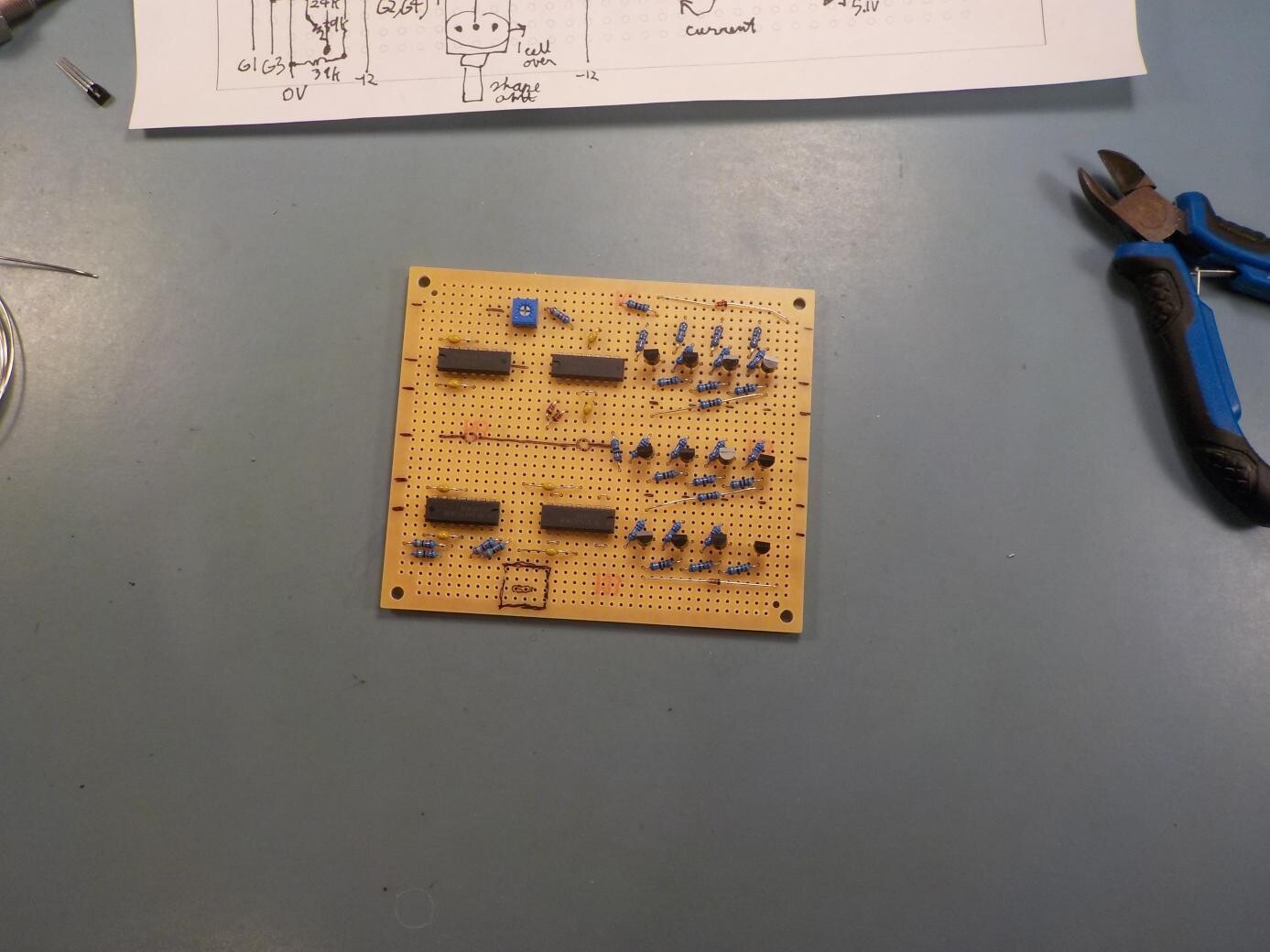
I started planning another stripboard for the shaper circuits - not only the modified Gilbert sine circuit, but also the shapers I had designed to turn the core's native triangle and square waves into sawtooth and variable-width pulse waves. Two buffer amps (for the native waveforms), two basic shapers, and the thirteen discrete transistors of the quadrature Gilbert shaper made for a lot of circuitry to pack onto one stripboard.
Here it is half-assembled. Note the transistor grid at right.
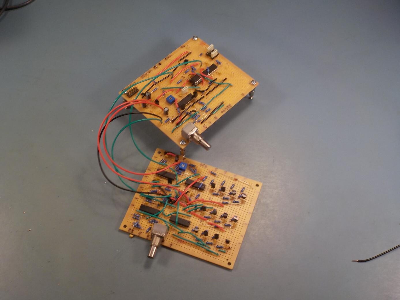
I added the rest of the components and wired it up to the VCO core board. At centre right on the core board you can see an IC socket I added for the capacitors in the sync circuit, because I wanted to swap out different values on those to choose the ones that would work best.
The stripboard version tested pretty well and I decided I could go ahead with designing a module around this circuit and building a more serious prototype.
Sine shaper output looks about like it should.
The voltage transfer function looks basically right, but it seems like one of the transistors isn't quite "firing" as it should. I think it may have been damaged by an earlier wiring error that put too much current through it. This isn't serious enough to be worth spending a lot of time debugging when I'm planning to build a PCB version anyway.
The pulse shaper output - which is being voltage-limited by Zener diodes in an op amp feedback loop - gives tops that are too rounded, as well as being too low voltage. This is with 5.1V Zener diodes back to back, so we might naively expect the top and bottom voltages to be about 5.7V (one diode's reverse breakdown plus the other's forward drop). It's actually much less, because the diodes start to conduct a little bit significantly before their official breakdown voltage, the op amp only needs a little bit of current to limit its output, and the diodes' high impedance at low current makes the whole thing more of a gentle back-off instead of a sharp cut-off. I remember facing a lot of similar issues in designing the Fixed Sine Bank, which also uses Zener diodes inside a feedback loop to limit output voltage. There, the gentle back-off is desirable (because it means lower distortion in the sine waves) but I went through a bunch of prototypes trying to get it to happen at just the right voltage. Here, because I want a sharp pulse wave, I don't want the Zeners to be gentle.
In order to get good results from the Zener diodes it seemed necessary to run them at much higher current; but the constraint of keeping 100k impedance for the PWM input (to remain in line with Eurorack standards) made that tricky. I tried creating a resistive "current divider" to make the Zeners see much more current than would actually be applied to the op amp input, and that helped a little but the output waveform was still much more rounded than I liked.
After some more testing (no image for this one yet) I decided to stop trying to keep the op amp out of saturation and just go open-loop, basically abusing it as a comparator, with the Zeners applied to the output. I'd been resisting that because of possible timing issues with the op amp (sometimes they take a while to get out of saturation) but it really seemed the best way to go, and upon testing, the time delay seemed to be acceptable and the waveform was nice and sharp-cornered.
How about the sawtooth shaper? When I first wired it up and testing it, it produced results that were completely wrong.
I figured maybe I had the polarity of one of the inputs wrong or something, and I went back to the simulator and simulated different build mistakes until I found one that gave similar-looking results. It turned out that wiring in a 2N7000 MOSFET backwards caused the simulator result to look like what the stripboard was doing, and when I went back to the stripboard and checked it carefully, sure enough, that was what I'd done.
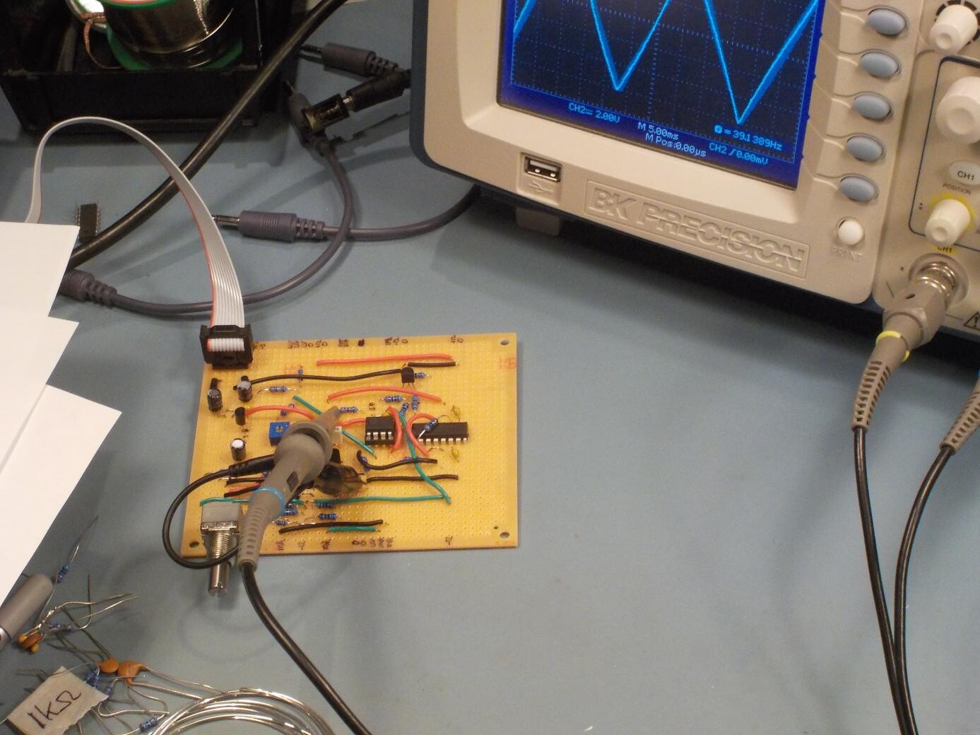
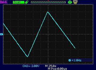
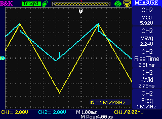
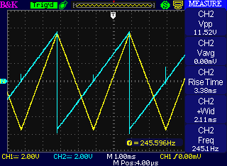
With that corrected, the sawtooth output looked good. The glitches at zero crossing visible in this scope shot will be smaller or absent in the real build because the compensation capacitor will eat them - I deliberately left that out on the stripboard because I wanted to see how big the glitches would be without it.
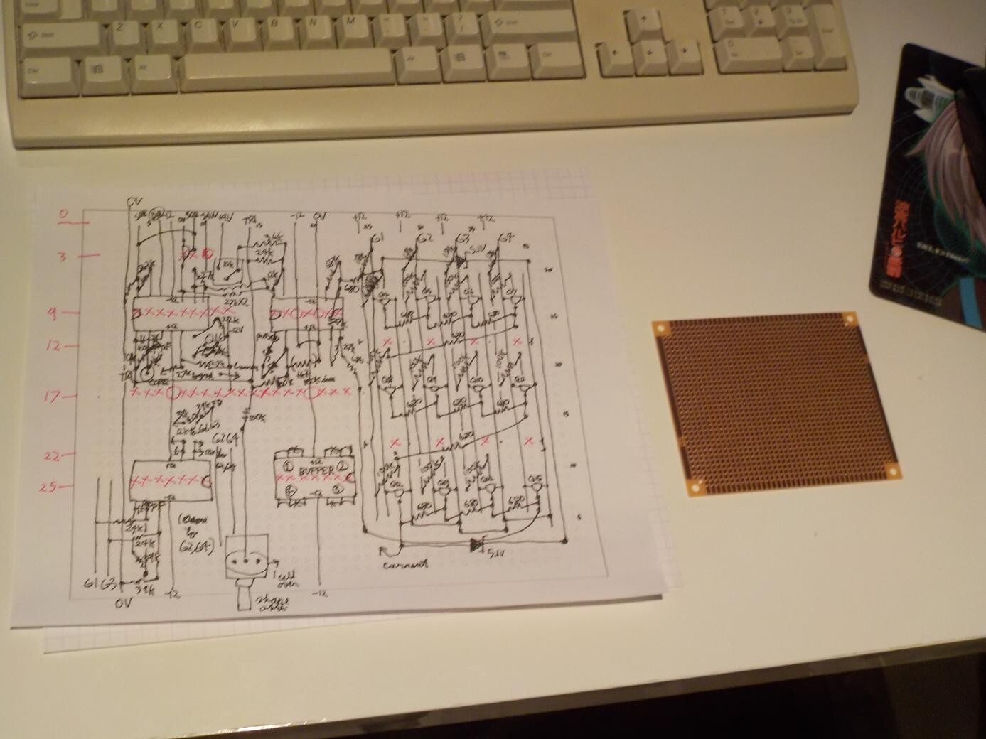
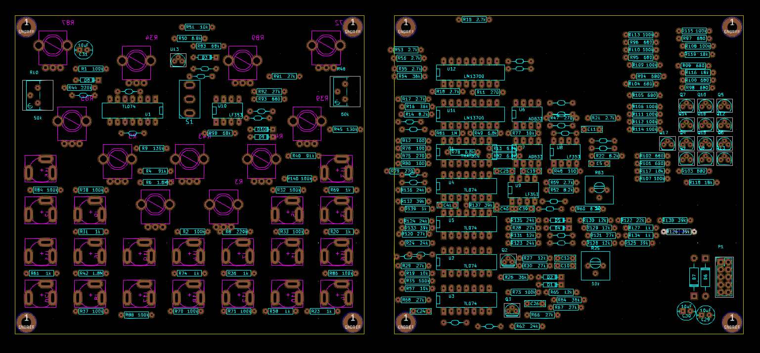
Now I wanted to proceed with building a real prototype module, with real etched circuit boards. I had to decide how big the module would need to be in order to have enough space on the PCBs and the panel for everything - not too big because people don't like large modules, but still big enough for it all to fit. Here's an attempt at fitting all the components onto boards sized for a 24HP module with two boards. I could probably have made it fewer HP if I'd gone to three boards (like the Leapfrog VCF), but the three-board design of the Leapfrog has always been an issue because it doesn't fit in everybody's case. I wanted this one to be shallower if at all possible, and anyway, making the panel any smaller would make it difficult to fit in all the knobs and jacks with room to patch it.
I actually did a tentative PCB design before I'd worked out all the issues on the stripboard. That necessitated ripping up some of the already basically finished design and rearranging components to accommodate the changes I decided to make in the pulse shaper circuit once I figured out the issue with the Zeners. Part of my reason for doing it in this sequence was that PCB routing is fun and I don't mind having the excuse to do it a little more. It's also a general fact that I tend to get a better, tighter layout on the second try, so there's a lot to be said for the old adage of "Plan to throw one away, because you will anyway."
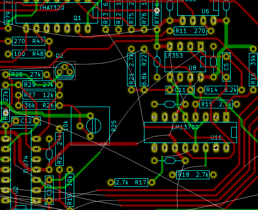
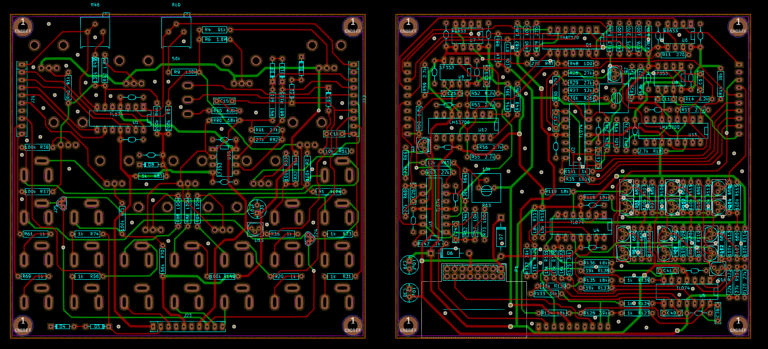
More or less final version of the PCB routing. At this point I still had to make the silkscreen art a little prettier, but I was close to ready to send the PCBs off to the prototype manufacturer in Shenzhen. Because of the global trade disruption associated with COVID-19, I really wanted to get the PCBs into the pipeline as soon as possible; the rest of the prototyping would probably end up waiting on them. But haste makes waste. Shortly after sending off the design, I discovered a minor issue with the normalling for the PWM input jacks. I can fix it with so-called green wires in my prototypes and maybe even in early production of assembled modules, but I will want PCBs that don't need patching to include in DIY kits, so that means at least one more board revision before I can produce DIY kits.
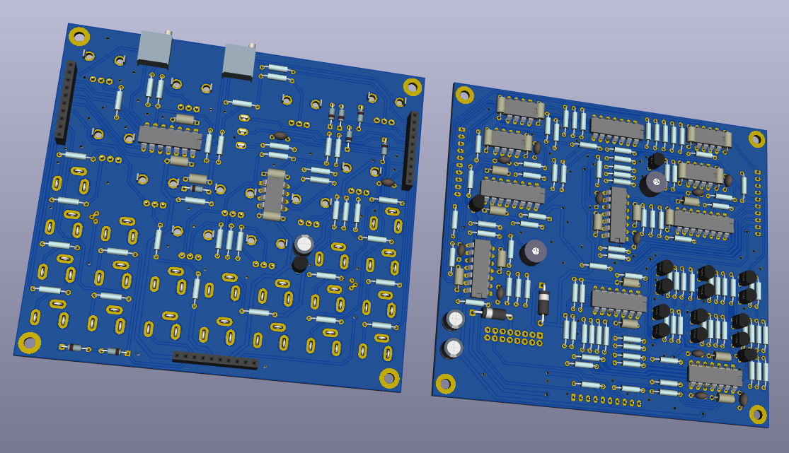
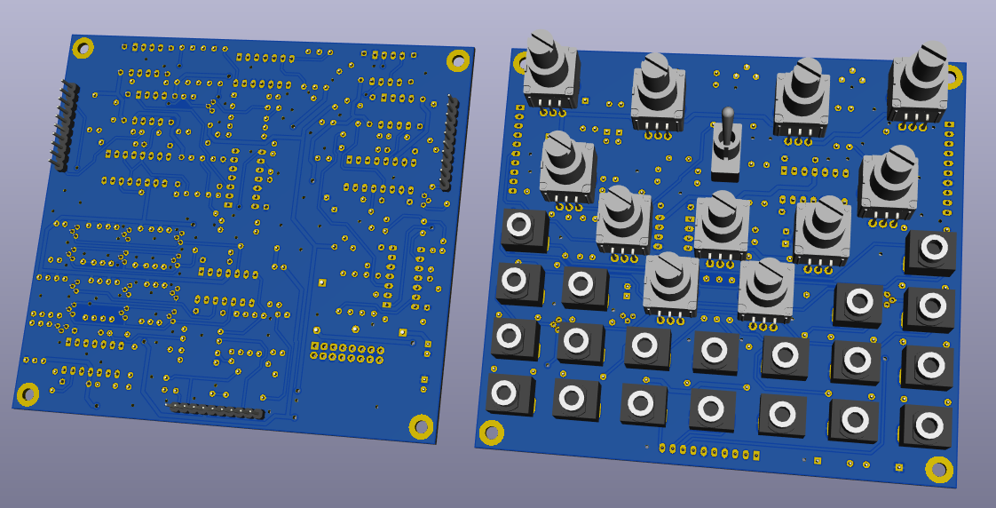
Some KiCAD 3D mockups of the boards.
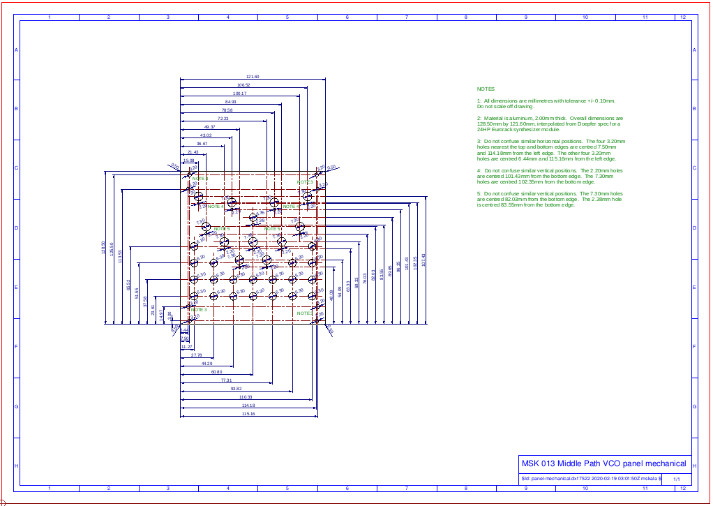
While waiting for the prototype PCBs, I had time to start doing the mechanical drawings I'd need to get the panels made and eventually to include in the manual. First I did a 2D drawing of the panel with all the hole sizes and locations.
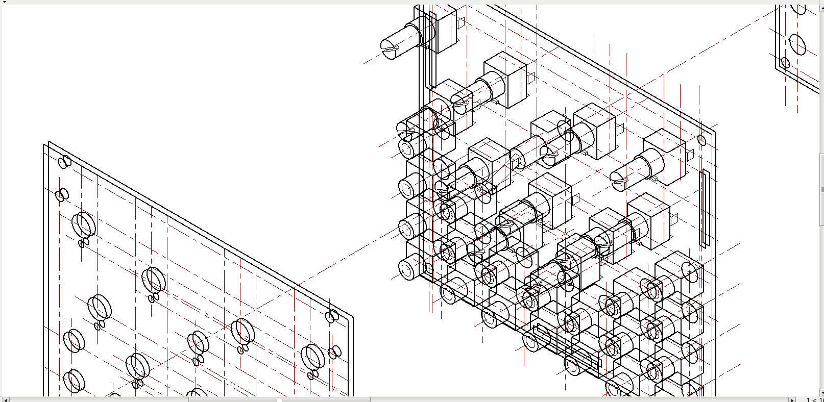
That was the basis for the isometric 3D exploded assembly diagram. I do these in the QCAD 2D drafting package, leveraging my old pencil-and-T-square skills from way back in high school. The results are pretty but it requires a lot of manual work because the computer is basically simulating just what I'd do with a pencil: draw all the lines first and then erase the parts you can't actually see, one line at a time.
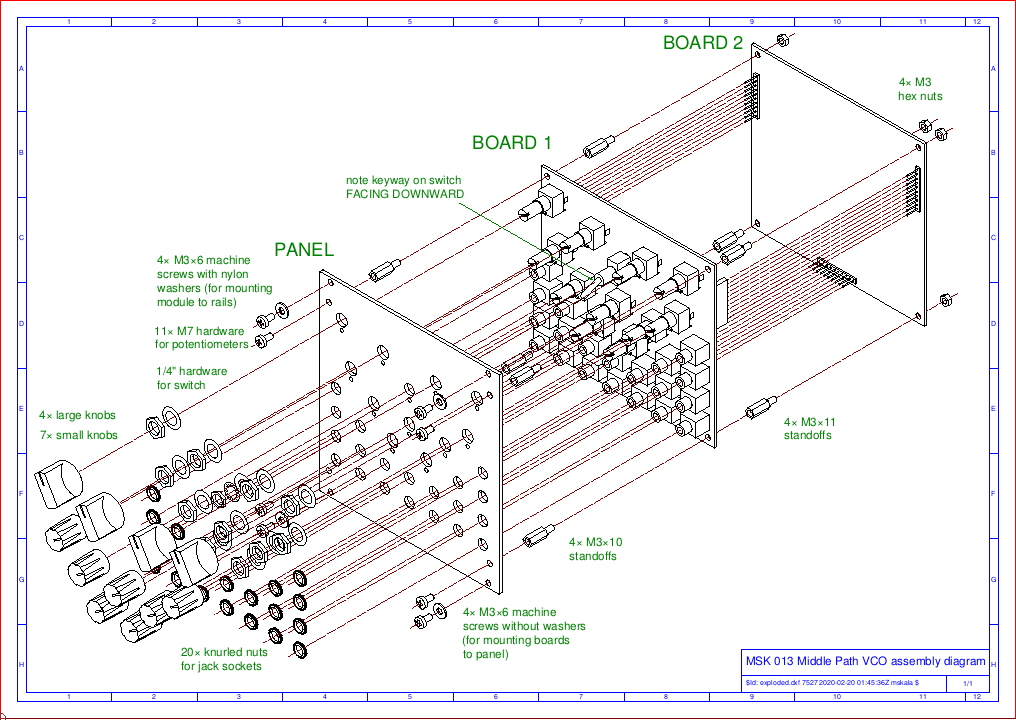
Finished version of the exploded diagram.
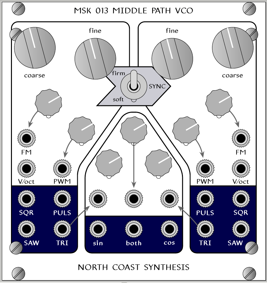
Having all the hole positions worked out also meant I could design the art for the front panel and make a mockup of that.
And that's where I stand with development. I have a few more things to order before I can build a full module prototype, but that is mostly waiting on the PCBs - which may be delayed a bit because of the global trade situation. As a result I don't have a firm timeline for when this module will be available; some time this calendar year, at least. I also haven't determined pricing yet. But I hope you've enjoyed this peek into the development process, and I hope you'll want to buy the module whenever I do have it available.
◀ PREV Ambient chord progressions || Design mistakes in synth schematics NEXT ▶