A stripboard Eurorack power cable tester
2021-10-09 eurorack power electronics stripboard
Here's a little project I put together to solve a specific problem: checking power cables for shorts. I made it using the parts I had on hand, and if you build one yourself you may well end up wanting to make changes, so I'm not going to prepare a complete set of documentation or sell kits or anything. I don't think it's going to be popular enough for selling them to be profitable. But if, like me, you're in a position of needing to check a lot of power cables, you might find these notes useful in designing your own tester.
All my products come with ribbon power cables, which I prepare myself by crimping insulation displacement connectors (IDCs) onto bulk cable. The process is pretty reliable - when I make a cable, it's usually good - but no manufacturing process is perfect. It's inevitable that a few of the cables I make will be defective, and it's important to detect those before I pack them into products and send them to customers. The worst, and most common, failure mode is that if the cable is a little bit misaligned when I crimp the connector to the ribbon, then the blade inside the connector that is supposed to cut through the insulation and make contact with one wire will actually hit two wires that carry different voltages. Then when the cable is plugged into a power supply, it shorts out the power supply. So it's important to check cables and make sure they won't do that.
In this video from 2019 you can see me making power cables and checking them for shorts with a multimeter continuity test. I only actually included the test for one cable in the video, because it's repetitive: every cable has to be tested the same way. It's a fiddly, annoying process that consumes a lot of labour.
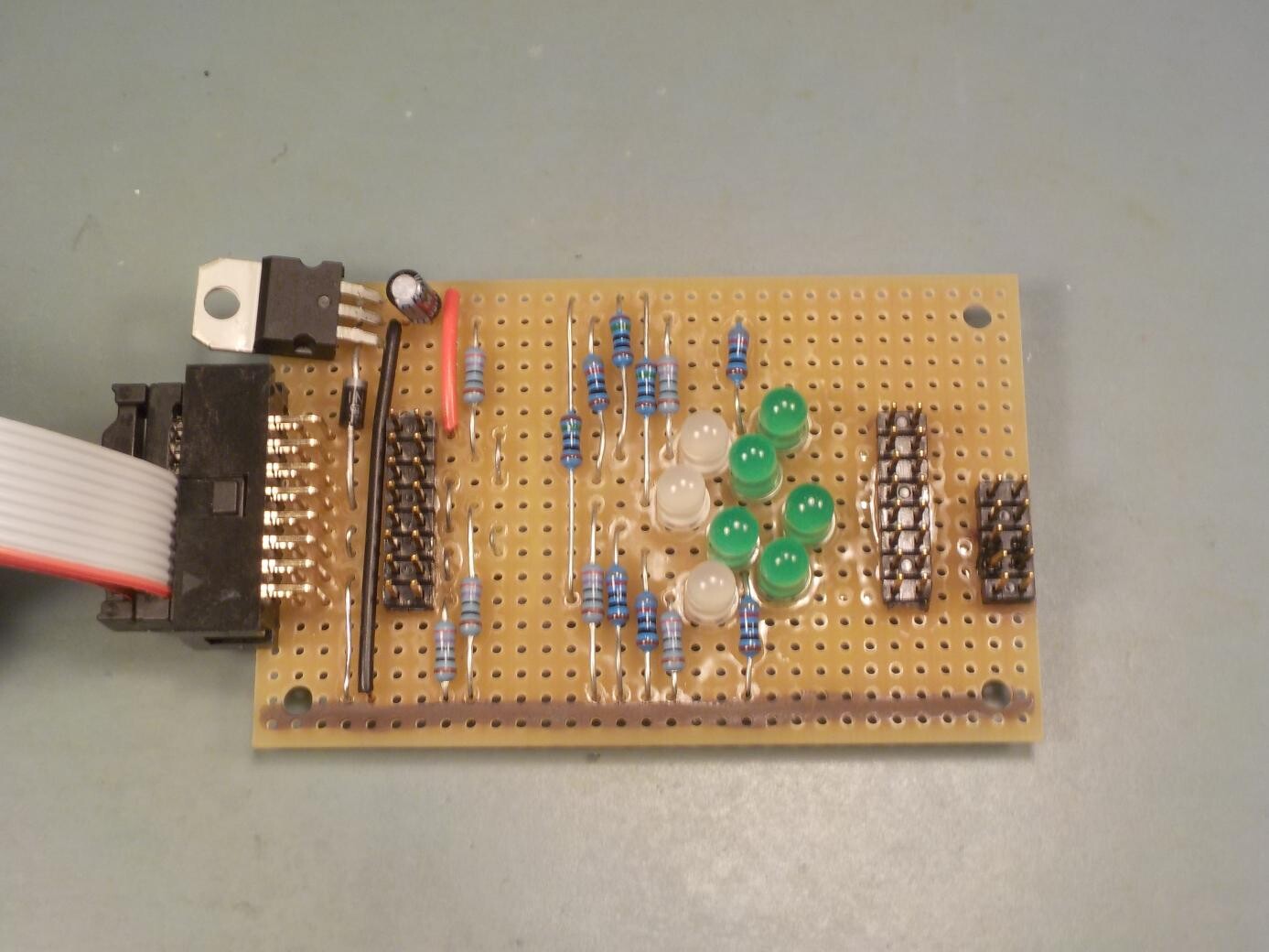
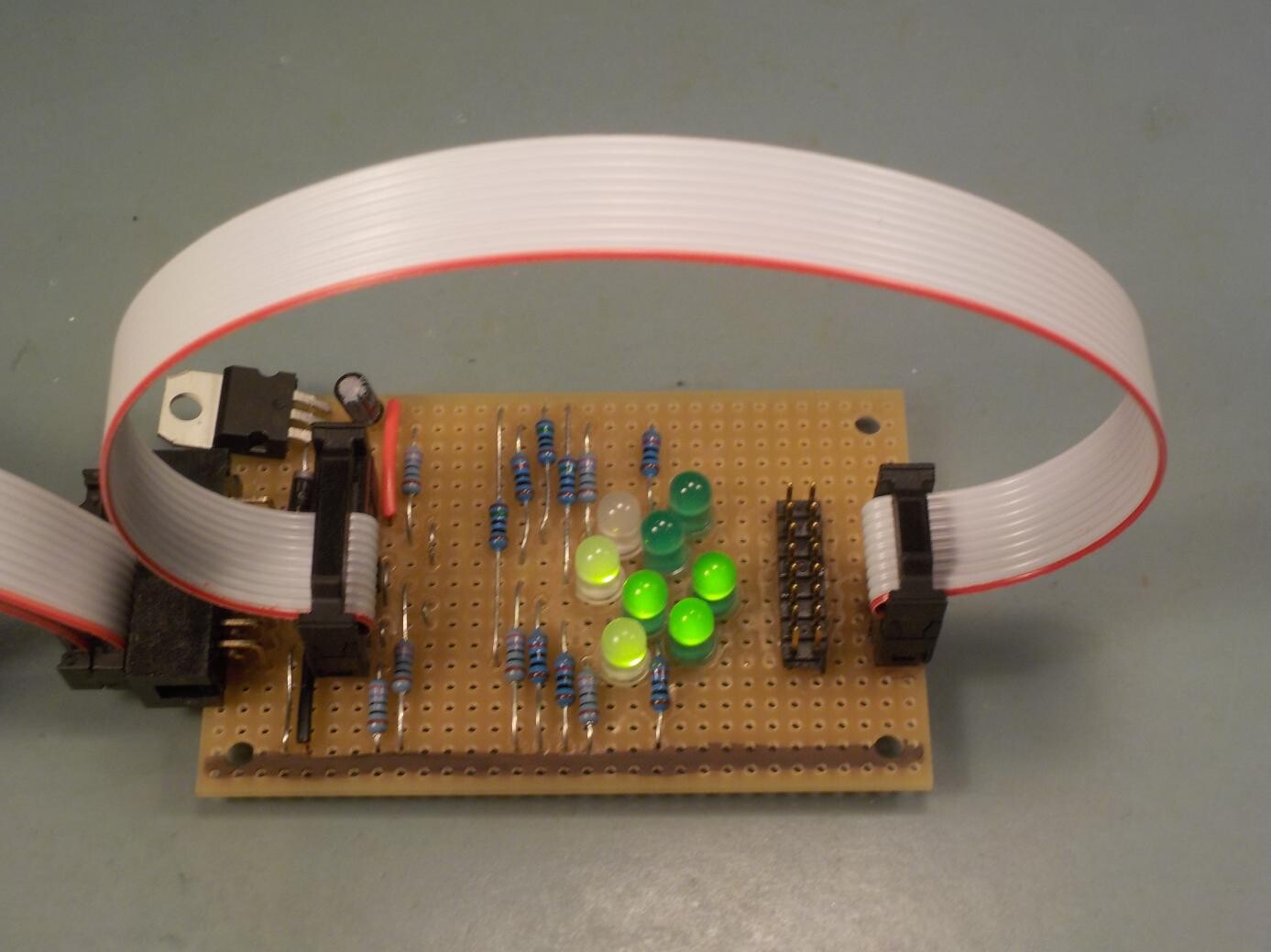
Here's the tester I built. It fits nicely on a small stripboard I got from Tayda. Stripboard is probably familiar to many of you. It's a piece of fibreglass circuit board with pre-drilled holes on a 0.1 inch grid (which will fit most through-hole components). On the other side, not shown in the photo, there are copper tracks, horizontal in this case, connecting all the holes in each row. So if I solder two things into the same horizontal row, they end up connected. For instance, in the photo I'm using the second row of holes up from the bottom as a ground (0V) connection. All the resistors in the lower half of the photo are connected into that row, and all go to ground.
I can also change the board by cutting through the copper tracks with a sharp knife, so that two things in the same horizontal row will not be connected when there's a track split between them. The idea is that using a standardized piece of stripboard, maybe with a little bit of modification by cutting tracks, is more convenient for a one-off project than going all the way to a customized etched board. I keep a stock of stripboard on hand for prototypes, custom production tooling, and so on. It's popular for hobby projects, especially in the guitar-pedal world, where people like to share circuit designs that can be built from generic parts without going to the trouble of making and distributing etched boards specific to a project.
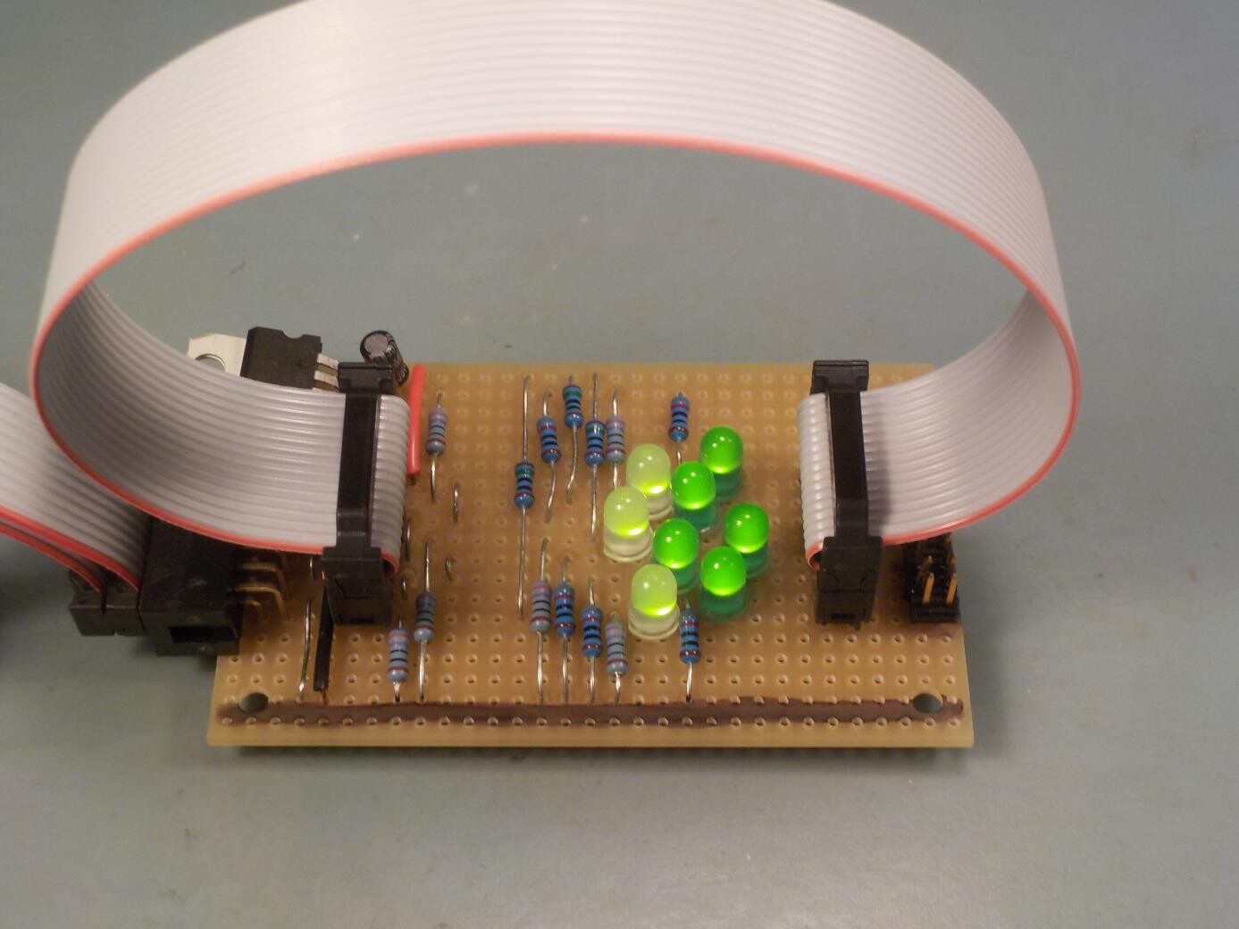
My cable tester plugs into a 16-pin Eurorack power supply, which I have on my workbench anyway for testing modules. That's at left in the photo. The cables I'm testing always have a 16-pin connector on one end for plugging into the busboard, and then either another 16-pin connector, or a 10-pin connector, on the other end for plugging into the module. So to test a cable I plug one end of the cable under test into the header on the left, and the other end into the appropriate header (16-pin or 10-pin) on the right. As usual in Eurorack, the cable stripe goes at the bottom. Eight LEDs glow green to indicate that the 16-pin cable is making a connection, without shorts, on every pair of wires.
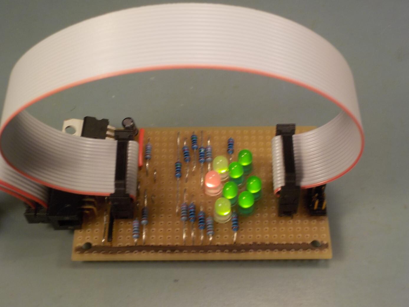
The left ("busboard") connector on the tester places specific voltages on the cable. Then the cable, once attached, connects those voltages across to the right ("module") connector, where a network of resistors and LEDs detects whether the correct voltages are coming through. There's an LED for each pair of wires in the cable (1 and 2; 3 and 4; and so on). Eurorack always puts the same voltage on the two wires in a pair like that. The LED for a pair goes green if the cable makes the connection, and most of the LEDs in the tester are simply green LEDs that can be on or off. But there are also three red/green LEDs that will go red if their wire pair is shorted to the wires on either side. With six different voltages or signals on the Eurorack bus, three red/green LEDs are just enough to indicate this kind of short.
For a 10-pin cable, which only carries three voltages on five wire pairs, only five of the LEDs light up.
So, how does it work?
I've prepared a PDF file of the schematic and stripboard layout. The "busboard" side connects the 1/2, 9/10, and 13/14 pin pairs to ground through 270Ω resistors. Those are the pin pairs corresponding to red/green LEDs; more on them later. All the other pins go directly to a +9V supply regulated down from the 12V input.
On the "module" side, the pin pairs with plain green LEDs just go through the LEDs and 820Ω current-limiting resistors; so if a given pin pair makes a good connection, then the green LED is just in a basic current-limiting resistor configuration and it lights up normally, as described in one of my earlier articles on analog LED drivers.
In the event that the cable shorts one of those +9V voltages with a neighbouring signal, that neighbouring signal will be one of the ones that goes to ground through 270Ω. Then there is more load on the power supply, but the power supply will keep the voltage at +9V and the green LED remains on.
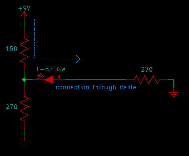
Now, what about the other signals in the cables, the ones with red/green LEDs? Those connect to ground through 270Ω at the busboard end, and through the red/green LEDs to 150Ω/270Ω voltage dividers at the module end. Here's how it looks in the normal case when there's a good connection and no short.
The voltage divider has an open-circuit output voltage of about 5.8V, with an output impedance of 96Ω (calculated by putting 150Ω in parallel with 270Ω; see my earlier article on series and parallel equivalents). Instead of drawing the voltage divider as two resistors going to +9V and 0V, we could replace it by its Thévenin equivalent circuit of a 5.8V voltage source in series with a 96Ω resistor, and get correct answers to questions about the voltages and currents that will be seen by other things connected to the voltage divider.
Estimating the LED voltage drop in green mode as 2.2V, the LED and 270Ω resistor, connected to the voltage divider which is equivalent to 5.8V through 96Ω, give an LED current of 9.8mA (computation: 5.8V-2.2V gives 3.6V, through a total current-limiting resistance of 96Ω+270Ω=366Ω), in the direction shown. This is the same LED type used in the MSK 010 Fixed Sine Bank and, as in that module's schematic, I use the convention that forward bias of the LED symbol in the schematic is for red, and reverse bias of the LED symbol is for green.
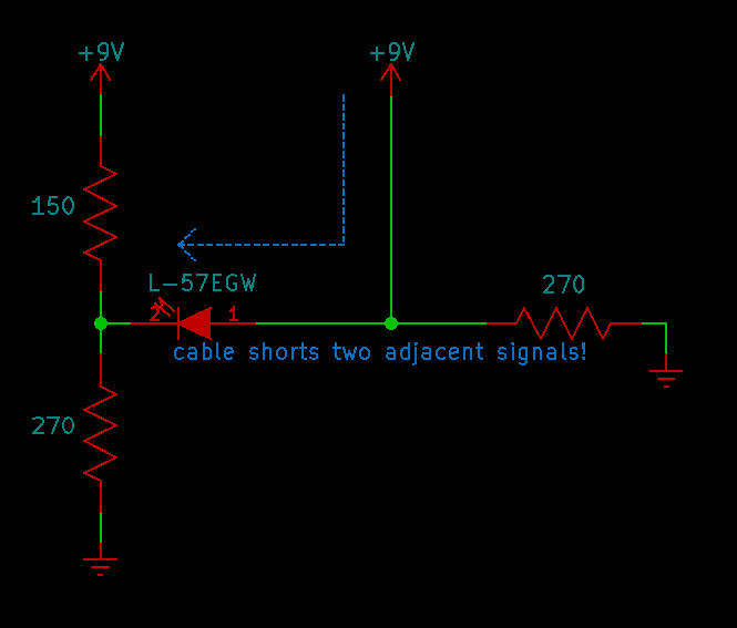
If the cable shorts the line that should be going to ground through a 270Ω resistor into an adjacent signal, then that adjacent signal will be +9V directly from the power supply. The 270Ω resistor at right in the diagram below will carry a fair bit of current but will not affect the LED, whose rear end is lifted all the way to +9V.
In that case, using a 2.0V voltage drop estimate for the same LED in red mode, we can compute 9.0V-2.0V-5.8V = 1.2V, divided by the 96Ω impedance of the voltage divider, and find that the current through the LED is about 12.5mA in the direction shown. The LED lights brightly red.
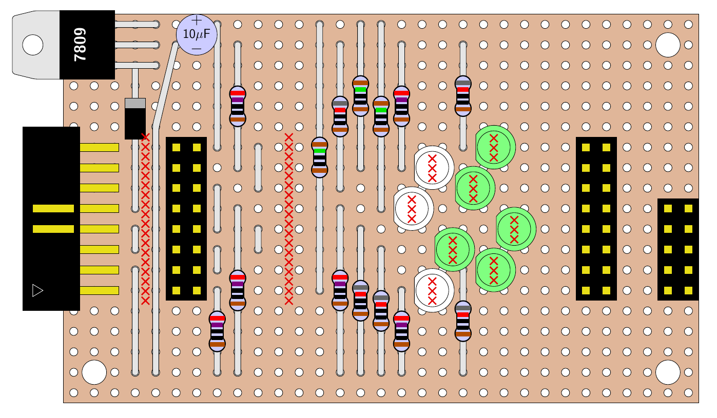
Here's a drawing of the stripboard layout, as shown in the PDF file. The rows of red crosses show the places to cut the tracks on the back side of the board: between the power connector and the "busboard" connector, between there and the "module" connectors, and under each of the LEDs. This layout is spread out to cover the board I had; there are some rows and columns unused, and it's not meant to be as small as possible.
My tester does not detect every possible thing that could go wrong with a Eurorack power cable. If one of the wires in a cable pair is open, failing to make a connection at all, the LED will still light as long as the other wire in the pair makes a connection, because the tester is connecting the two wires in parallel. Similarly, it won't detect shorts between two wires that are at the same voltage, and it won't reliably detect more complicated miswiring between more widely-separated wires, such as could happen in a cable with individual loose wires connected by hand. This tester is really aiming for one specific fault, the short between two adjacent power voltages. But that happens to be both the most common and the most damaging failure mode for the Eurorack cables I make, so it is the one I want to detect. The tester works pretty well for its intended application.
If I wanted to make a fancier one, I think I'd look at doing it digitally. I might have a microcontroller send serial messages along each wire, and another microcontroller (or the same one, but I'd probably run out of I/O pins) look for those messages at the other end. Then I could detect connectivity of each pin to each other pin, and specifically diagnose all possible open and short faults. For my own cable-making that level of testing is probably excessive, but it would be fun, and I have some extra microcontroller chips now as a result of buying some for my current development project that ended up not being the kind I wanted to use.
◀ PREV Fat sounds and thick pads || Leaving BigCommerce NEXT ▶
