Temperature compensation with NTC thermistors
2017-10-22 science! MSK 007 electronics design
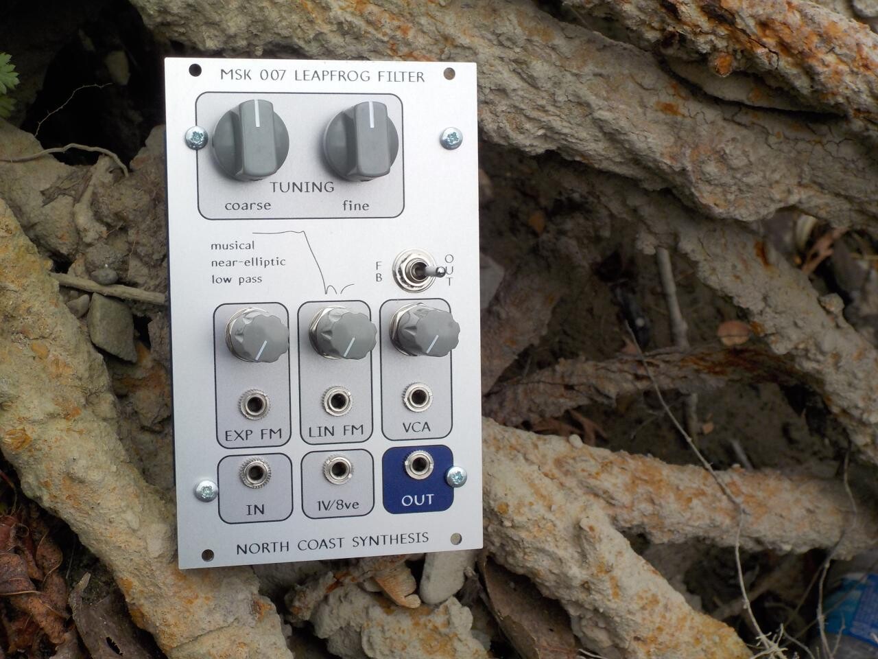
The panel contractor says they dispatched the first production batch of MSK 007 Leapfrog VCF panels to me on Friday, and those are the last remaining physical items needed before I can launch the module; so I'm still hopeful that I can aim for a launch by the end of the month. That means I need to finish up the last few documentation items; one of them is a description of the exponential converter temperature compensation circuit, and that's an interesting enough item to be worth a Web log posting of its own.
To warm up: in the modular synth world we talk about modules being "voltage controlled," but very many analog circuits are really current controlled. An oscillator or filter will usually need its pitch to be set by a current proportional to the frequency. I've sometimes toyed with the wacky idea of an entire synth format that would be current-controlled throughout, but what everybody does in real life is use voltages to transmit control between modules, and then convert voltage to current inside the module to actually drive the circuit.
Moreover, there's an issue of the shape of the pitch response. Oscillators and filters usually want their control currents to be linear in frequency. So many µA equals so many Hz. Double the frequency (which means going up one octave) and you double the current. Some synthesizers are voltage controlled on a similar system, called Hz/V, where each volt of control voltage raises the frequency a given number of Hz. But it's an uneasy combination with human perception, which is logarithmic. The difference between 100Hz and 200Hz sounds like one octave, and so does the difference between 1000Hz and 2000Hz, even though in frequency terms one is ten times as much as the other. That tension between human perception and physical frequency, combined with certain engineering issues that crop up when one tries to handle both huge and tiny voltages in the same circuit, make it appealing to use a different control system where each volt corresponds to doubling the frequency. That is the V/oct system used in Eurorack. Voltage is logarithmic in frequency, and frequency is exponential in voltage.
The oscillator and filter cores still need linear currents even if the modules exchange logarithmic voltages, so there's a need for exponential voltage to current converters which perform the translation. These "expo converters" are nearly always based on BJTs (bipolar junction transistors), which happen to have a nearly perfect exponential voltage-to-current response just as a natural consequence of their operation. Here's an equation from the simplified Ebers-Moll model of transistor behaviour:

That may look complicated, but the important thing to understand is that very much of it is either constant or negligible. The variable Isat is a constant associated with the particular transistor design; it is very small (femtoamps to picoamps), which means that when the transistor is passing any usefully nonzero amount of current, nearly all the current will be associated with the exponential and we can ignore the -1. Then q and k are also constants (respectively charge per electron, and Boltzmann's Constant describing the relationship between energy and information), and all that we really need to know about are the parts I've highlighted with colours: current through the transistor is an exponential function of base voltage divided by temperature. That is absolute temperature, usually measured in Kelvin. A hot Summer day might be 300 on this scale, and water freezes at 273.15. So we can just scale our control voltage appropriately, feed it into the transistor's base, and the transistor will pass a current that we can use to control our VCO or filter, right?
Not so fast! The current is not only exponential in the voltage, but exponential in the voltage divided by the temperature. And in practice that's a big problem, because people are very sensitive to small fluctuations in frequency. If the temperature of the circuit is around 300K (a little higher than room temperature, and maybe typical inside a synthesizer case), then a one-degree change in temperature is more than 0.3% of change in the voltage response. How much that may change the absolute frequency of a module depends on the absolute voltage; but we can say that it's a change of about 4 cents per octave in the V/oct tracking response, for every degree (Centigrade or Kelvin) of temperature change. If you build an uncompensated exponential converter on a breadboard and then breathe on it, you can hear it go out of tune. Most filters may be able to get away without using temperature compensation as long as nobody is using them in resonant mode as sine-wave VCOs; but true VCOs need to track better across a range of temperatures, and so does the Leapfrog because of its extra-sharp response curve.
The usual first step in temperature compensation is to use a second transistor, as near as possible to identical to the first. In particular, it should have the same value of Isat. People talk about matching transistors for equal VBE, but that is just an indirect way of getting at the value of Isat, which is hard to measure directly; they match for equal VBE at a fixed IE and that has the effect of matching Isat. One transistor is set up in a feedback loop to always pass a fixed reference current and find its own value of VBE do that. Then the desired control voltage is applied as a difference across the two transistors, and the second transistor's current output is the exponential current. This technique cancels out the first-order (temperature only) temperature dependence of the transistors; at zero control voltage, and if we could be sure of always keeping the two transistors at exactly the same temperature, it would be perfectly temperature-stable.
Here's an MSK 007 exponential converter cluster; you can see the two transistors bound together face-to-face in an effort to keep them at the same temperature. Also included in the group hug is a blue NTC thermistor, discussed later in this article. Other designs do things like asking for special transistor pairs that are manufactured as parts of a single silicon crystal. Silicon's very high thermal conductivity (a property it shares with diamond, stemming from their closely similar crystal structure) reduces any thermal differences across the crystal.

But to cancel out the second-order (temperature times voltage) dependency, we need to scale the control voltage in proportion to the absolute temperature. Just comparing against a second transistor is not enough. So a typical approach is to say "We want gain proportional to T, the value of T increases by 3350ppm per degree, so we want gain that increases 3350ppm per degree." Do you see the problem?
One problem is that that's attempting to approximate a linear function with an exponential. The value of T only increases by 3350ppm per degree when T happens to be about 298. (That is why you will sometimes hear other numbers quoted, such as 3300ppm/°C or 3360ppm/°C - they're all correct, just at different reference temperatures.) The way temperature really increases is "one degree per degree." However, over a small enough temperature range this isn't a big deal; the difference between the linear function of temperature that you want for gain, and the "3350ppm per degree" exponential function, is small enough not to matter.
The more important problem is that making your gain increase this way isn't as easy as it may sound. You can buy temperature-sensitive resistors in a range of different temperature coefficients, so you could pick one of those with a coefficient of 3350ppm/°C and use it in the feedback loop of the op amp you probably already needed for other reasons, to make the gain scale in proportion to absolute temperature. But these "tempco" resistors are expensive and hard to find, and they may not have the right nominal values, and the through-hole versions keep getting discontinued, and so on. They've become a bugaboo for SDIY hobbyists.
When I designed the MSK 004 Octothorpe, I experimented with a fairly elaborate temperature compensation scheme using a Vishay NTC thermistor. This is a resistor whose value decreases instead of increasing when the temperature goes up. Its temperature coefficient is something like -24800ppm/°C near room temperature, but varies a fair bit depending on the temperature; it does not purport to be a pure exponential or linear function or anything like that. But it's a reasonably cheap device, not likely to go out of production or become a surface-mount-only component in the near future, and its temperature coefficient may have a tighter tolerance than that of readily-available positive temperature coefficient "tempco" resistors. In the Octothorpe I included the thermistor as part of a resistor network that also included a couple of trimmers. The idea was that if the thermistor varies a lot with temperature, then a series and parallel combination of it with some other non-temperature-varying resistors will vary less, and by adjusting the network carefully, I should be able to fit the temperature-resistance curve to what it needs to be to exactly compensate the transistor's temperature dependence. I am not the first or the only person to explore using NTC thermistors for synthesizer exponential converters. Rene Schmitz is one often-cited source for that; and Ian Fritz has written about variable-temperature-coefficient exponential converters.
I built the Octothorpe with an exponential converter of that design, and I tested it, and it worked! Sort of. In order to get good results I had to go through a complicated process of warming and cooling the module to different temperatures, measuring the response, computing correction factors, readjusting the trimmers, and trying again. It wasn't something I could reasonably inflict on DIY builders, much less do myself in a commercial production environment. For the Leapfrog, I simplified it down to a resistor network with only one trimmable element, the usual "tracking" potentiometer.

The schematic fragment above is a voltage divider that sits between the control-voltage processing op amp, which has a gain of -0.22 (thus, -220mV/octave input on the left of the voltage divider), and the two transistors of the exponential converter. In the top of the divider we have a three-resistor network including the Vishay NTC thermistor; in the bottom, it's just an adjustable resistance for overall scaling.
I chose the values for the resistor network (R67, R68, and R72+R77) by a lot of simulation and trial-and-error, using both ECLiPSe-CLP and Gnuplot to fit the curve to the data sheet resistance values for the thermistor, over a reasonable temperature range. Here's a plot of the results.

The line-connected purple points on the chart show the output of the voltage divider, scaled to the absolute temperature. Perfect temperature compensation would be a horizontal line at 1.000, as shown in green. If the plotted value is 1.001, that means the output voltage is off by 0.1%, meaning that the tracking will be out by 1.2 cents per octave, assuming everything is properly adjusted, resistors have their nominal values, the NTC thermistor itself behaves exactly as specified, looking only at the error in the temperature compensation circuit, and so on. The Leapfrog circuit looks pretty good over the range from 10°C to 40°C, which covers typical real-life use of synthesizer modules. Outside that range the accuracy starts to decrease; but note that the same is true for the cyan curve, representing behaviour of a more popular +3350ppm/°C "tempco" resistor, because of the difference between the exponential behaviour of the "tempco" and the transistor's actual inverse-linear behaviour. Overall, I think the NTC thermistor circuit is quite acceptable for an analog synth filter, and in practice with the prototypes I've built and tested, it does seem to keep the frequencies about as stable as I want them to be.
◀ PREV The Celebrated Leaping Frog || Preferred values for resistors and capacitors NEXT ▶