The Celebrated Leaping Frog
2017-10-15 news MSK 007 electronics design
I've spent most of this week working on the second and third prototypes for the Leapfrog VCF. I'm hoping to have this product available for sale by the end of the month - maybe in time to have some kind of spooky Halloween tie-in for the launch.

I did most of the electrical design before I started the company, and at the time it wasn't intended as a commercial project. The green-board prototype (still visible on the shop page, though I'll eventually update that with newer photos) came from that effort, and it had a number of issues that I knew would have to be fixed before I could even share, let alone sell, the design. Probably the biggest was that the panel potentiometers were all mounted backwards (!) - turning the main tuning knob, for instance, would give higher frequencies for counterclockwise and lower for clockwise, and the VCA/volume knob would give louder volume for counterclockwise and softer for clockwise. There were also issues with the panel layout (knobs too close together, a subject about which I've written before), tuning ranges, and so on. But prototype 1 was still good enough for me to record some demos. I more or less put it on the shelf while starting the company, and this month now that that's more or less up and running, I have the chance to develop the design further.
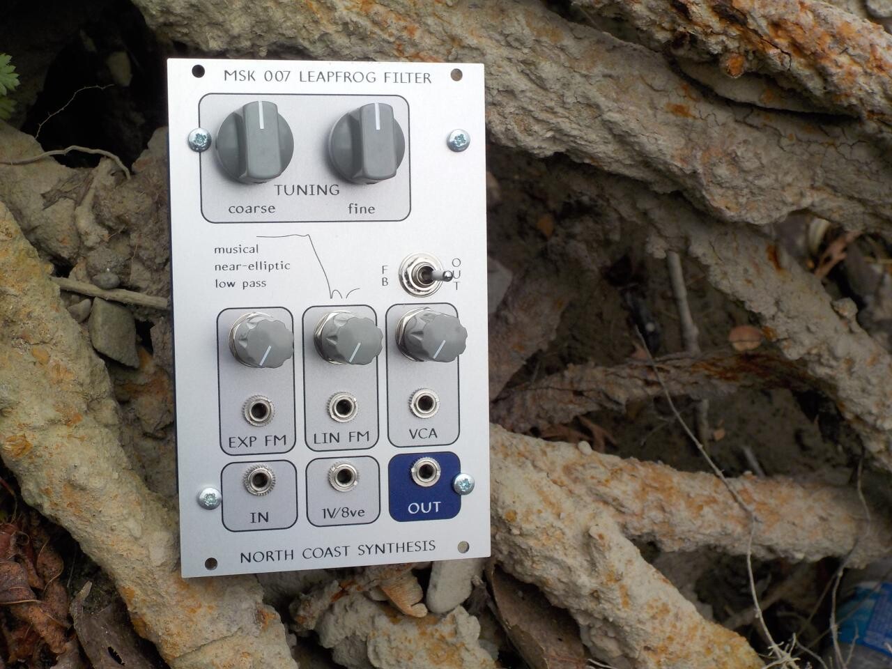
What you see in the photo above is the second prototype, with blue "version two" boards incorporating all the design changes I wanted to make after testing the first one. All the knobs go in the right direction this time, though I must admit I've gotten sufficiently used to having them backwards that I still sometimes try to turn them the wrong way on prototype 2 because I'm expecting them to go backwards like on prototype 1. That's likely a problem nobody else will have.
The main agenda item for prototype 2 was to do a whole bunch of testing - determine exactly what response curve it was producing, sort out the adjustment procedure for making it obey the intended response curve, determine whether any more design changes would be needed, and so on.

The Leapfrog's filter core contains five integrators, as opposed to the two integrators in the average modular synth state-variable filter. That is part of the reason the Leapfrog is a larger, more complicated, and more expensive module than people may typically expect for a filter; but that's what it takes to get the sound I wanted. In principle, optimal performance requires that each of the five integrators should have its time constant exactly right, and then the output mixer should mix together exactly the right proportion of each of the five integrator outputs - a total of ten adjustments in all, two for each of the five integrators. You can see the ten multi-turn trimmers for that on the back of the module (photo below), along with one more trimmer for core DC offset. The complete module also has two more trimmers on another board, not visible from this angle, for controlling VCA DC offset and volt/octave tracking. Beyond paying for the multiturn trimmers themselves, there is the labour cost of making 13 different adjustments on the module; this is a design on which most manufacturers would cut corners.

So, one of the important questions to settle with prototype 2 was how necessary the complete phase-difference adjustment procedure for these trimmers actually is. In experimenting with the first prototype I'd established a fairly complicated process that started with "pre-adjustment" on the PCB containing the trimmers alone, using just a multimeter, followed by full "adjustment" on the module as a whole, with all boards plugged together, feeding an external signal into it and watching the results on a digital oscilloscope. There is some careful design in the way the boards connect together, with some of the connections between parts of the trimmer-carrying PCB made only through the other boards when they are assembled, so that disassembling the module breaks up the resistor network into fragments that are easier to test with an ohmmeter. The full adjustment procedure is time-consuming and difficult; it requires measuring a bunch of phase differences among different test points while the module is powered up and filtering an input sine wave. The phases fluctuate a lot because of the feedback, my oscilloscope isn't all that good at measuring phase differences anyway (and I think it's typical of the scopes my customers will be using), and after each adjustment you have to wait for the phase to settle down and then try to find the middle of the range it's varying over before you know which direction to make the next adjustment.
This is a multiple feedback filter, and feedback loops are notoriously difficult to adjust. Each of the five time constant trimmers affects the behaviour of the entire filter core, so as soon as you adjust one, the others may all need to be re-adjusted. But on the other hand, one of the big advantages to the leapfrog topology is that in a certain sense it is optimally robust against component tolerances: if components vary, or trimmers are out of position (which is equivalent to components varying), the filter curve should remain quite stable. Other core designs attempting to achieve this response curve would be so sensitive to component inaccuracies as not to work at all. The multiple feedback loops, although annoying, help to compensate for errors. And my experience with prototype 1 was that even before I did any adjustment on it, when I just plugged it in impatiently right after building it, it still worked pretty well. Could I consider dropping the full adjustment procedure and depending on the pre-adjustment alone? If so, that would save a lot of time and effort both for me and for DIY builders. In particular, it would reduce the amount of potentially expensive test equipment needed to successfully build an MSK 007 kit.
The plot of test results on prototype 2 pretty much speaks for itself.

The overall shape of the curve is basically the same both with and without the full adjustment. There's just a little bit of extra insertion loss below the cutoff for the module when only pre-adjusted, and the slope looks a little less steep and (to the extent it's possible to measure, which is limited by the test conditions and equipment I was using) the attenuation above the cutoff may not be as good as it should be. So there is still some advantage to really doing the full adjustment properly, and I still plan to do it for the fully assembled modules I sell. But I'm declaring it optional for kit builders. Someone who only has a multimeter and not an oscilloscope can still expect to get very nice performance and shouldn't be scared away by the full phase-differencing adjustment procedure. That's the good news from the prototype 2 measurements.
The bad news was that (as I mentioned last week) the DC offset is bigger in prototype 2 than I expected. This filter is DC-coupled throughout. I thought hard about whether to do that and decided that yes, it's the right thing; but it means that all the DC offsets of all the LM13700 amplifiers (potentially significant on each one, and there are six of them) can add up around the feedback loops to give an unacceptably large offset at the module output. There are two trimmers meant to compensate for that, and they were designed (based on my measurements of prototype 1) to be able to apply what I thought should be a larger adjustment in either direction than component tolerances would ever make necessary. And it wasn't enough. Even with the core DC offset trimmer all the way at the end of its range I couldn't put enough trim onto prototype 2 to counteract its DC offset. I ended up modifying the prototype with an extra resistor soldered in parallel to the existing one that sets the adjustment range for the trimmer, and with that change I was able to get the DC offset to be reasonable - still larger than I really want, but small enough I can say it's just part of the unique charm of the filter.
So I figure I have to change the recommended value for that range-determining resistor. I'm now building a third prototype with what I hope will be the final value, and I'll see how it goes. I'm hoping that prototype 2 was near the worst case for component tolerances and prototype 3 will be trimmable to acceptable performance without requiring further modifications. If so, it's not a big deal - I can still sell these boards with little stickers over the offending component value and a careful explanation in the build instructions of what resistance should go there. There is no difference in the electrical parts of the circuit board, it's just a matter of mounting a resistor value in one place that is not what the board silkscreen says. And this is simply part of the calculated risk I took when I ordered the prototype batch of boards - buying a bigger batch saves money by reducing the price per board, but buying a smaller batch reduces the issues if design changes turn out to be needed.
Building the third prototype is a slow process because now I'm also taking the photos for the instruction book. Where I would normally stuff most of a board with components and then solder them all in one go, on this build I'm doing every component value as a separate step and taking a photo before going to the next. Everything has to be done in the same sequence I plan to write up in the manual, and it takes hours. So far I've finished two of the three boards.

On the board at left you can see the five silvery-coloured polystyrene integrator capacitors. Those are quite expensive, and (because they're made with pure tin foil, which is close to melting at solder temperatures) they're finicky to work with. You can't heat them too much when putting them in or they'll be damaged. When installed properly they do work well, though. In prototype 1 I used silver mica capacitors because I had some and I thought they would be cool to try, but those are even more crazily expensive and they have some disadvantages when used at audio frequencies. The polystyrene caps cost a little less and seem to actually be better for this circuit. In particular, with polystyrene caps prototype 2 is able to oscillate over a wider frequency range than prototype 1, even with the DC issues which aren't beneficial to the oscillation range. I'm interested to see what the results from prototype 3 will be, so I can start to get a clearer picture of how much variation there will be among individual filters. It seems likely there will be some variation, but that too is part of the charm of analog electronics. Every module will be its own slightly different thing, even before people get into "modding" them.
To support modding, the circuit board has extra pads for the integrator capacitors (even including a surface-mount footprint) so home builders can substitute other caps. NP0 ceramic would be worth a try; silver mica like I used in prototype 1 (though I don't particularly recommend it); or whatever else. I'd really like to try glass capacitors, but I don't think I can sell those because it's hard to get them except as old-stock military surplus. Glass capacitors are especially appealing to people building missiles (because they can withstand a lot of acceleration), and I don't want to get into selling anything with parts in it that could attract the wrong kind of attention to me from the export-control authorities. I've already had to go through one round of convincing a parts supplier that I'm not a steely-eyed North Korean missile man, nor a reseller acting on their behalf, and that was only over stupid audio panel controls that are not subject to any important export restrictions in the first place.
Further on modding, the Leapfrog module is designed so that pretty much all the components that determine the filter response curve are on just one of the three PCBs, the one on the back with the 11 trimmers. If you built that board differently (different resistor values and adjustments), you'd get a different filter curve. There are even some extra holes on the board for mounting components that other curves might require and this one doesn't. So although I'm launching it with just the near-elliptic low-pass response, there's a strong possibility of building other filter responses from the same basic design. High-pass, band-pass, maybe a "formant"-like filter with two band pass segments... there are many possibilities. With the right configuration it can produce almost any five-pole response, which basically means the curve can have five bumps on it. Referring back to the curve I measured for prototype 2, there's a bump near 0Hz, one near 733Hz, one at the cutoff of 1.0kHz, and then two more down in the stopband at higher frequencies off the right of the diagram - those positions chosen to optimize the slope of the cutoff. Having five poles allows for a fair bit of complexity, though not an unlimited amount.
What other filter responses will people want? I don't know, and given the cost of developing them, I'm not going to try to work out any such modifications before I sell some of these filters with the basic low-pass response. Each new curve requires some fairly involved calculations and then building a prototype to see that it really works. The Leapfrog project is already way behind schedule (I had been hoping to sell them before the end of 2016 and it looks like ten months later is the best I can hope for), and if the business as a whole is going to work, I need to see some real sales figures. But I'm thinking about what other responses people may want, and I'm thinking of staging some kind of promotion where people who buy the low-pass Leapfrog can place votes for what kind of response curve they want me to develop next.

◀ PREV Nucleosynthesis || Temperature compensation with NTC thermistors NEXT ▶