All about normalling
2022-04-27 electronics
If you plug a patch cable into an input jack on a module, the module receives the signal from that cable. What if you don't plug a cable into the input - what will the module do? Let's look into that in detail.
Symbols and terminology
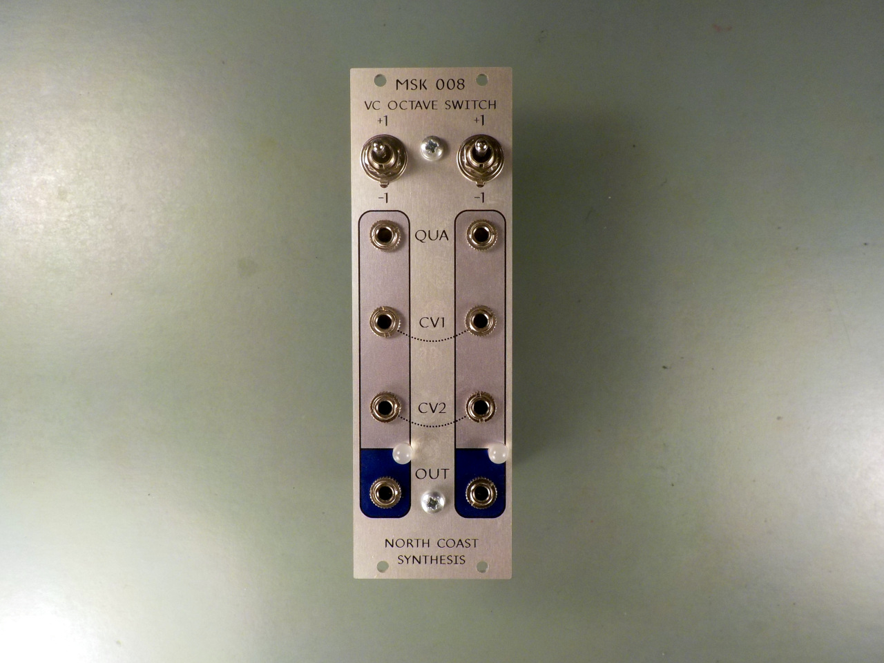
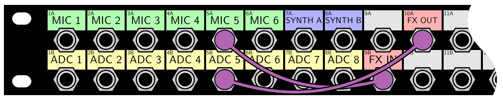
The term "normalling" refers to how inputs function by default when there is nothing plugged into them. Quite often, at least in Eurorack, inputs are normalled to other signals to provide some useful behaviour without needing to attach a cable. For instance, in the MSK 008 Octave Switch, each CV1 or CV2 input is normalled to the corresponding input on the other side of the module. Plug a cable into either CV1 input and the same signal drives both. Similarly for the CV2 inputs. The curved dotted lines in the panel graphics, connecting the pairs of inputs, are there to remind the user of this behaviour. The normalling is overridden if you plug cables into both sides. Then, they operate independently. With no cable plugged in on either side, the design of the circuit gives an effect equivalent to plugging in 0V. The QUA inputs are different: they normal to 0V and plugging into one does not affect the other.
You'll sometimes hear normalling called "normalization." I've done that myself occaisionally - it's in some of my module manuals, or will be until I get around to changing it - and so have some other designers more famous than me. But I think it's really better to use the word normalling for the connections automatically made when nothing is inserted in a socket. Normalization in audio is better reserved for adjusting the amplitude of a signal to some standard level (usually near the maximum the system can handle). For example, many MP3 encoders have a normalization feature, so that you can listen to your playlist in random shuffle mode and have it stay at a comfortable listening volume without needing repeated adjustment. That usage is consistent with the meaning of "normalization" in mathematics, for things like probability distributions.
Normalling is often accomplished by means of normally closed (NC) switching contacts in the jack sockets. As well as the contacts that will make connections with the plug, the socket has at least one additional place to connect a wire or circuit board trace. Two pieces of metal in the socket touch each other and form a connection when there is no plug inserted, but inserting a plug bends one of them away, breaking that connection. The circuit input is wired to take its signal from the plug if there is one, and otherwise from some internal source. Here are some schematic symbols for jacks with switching contacts.
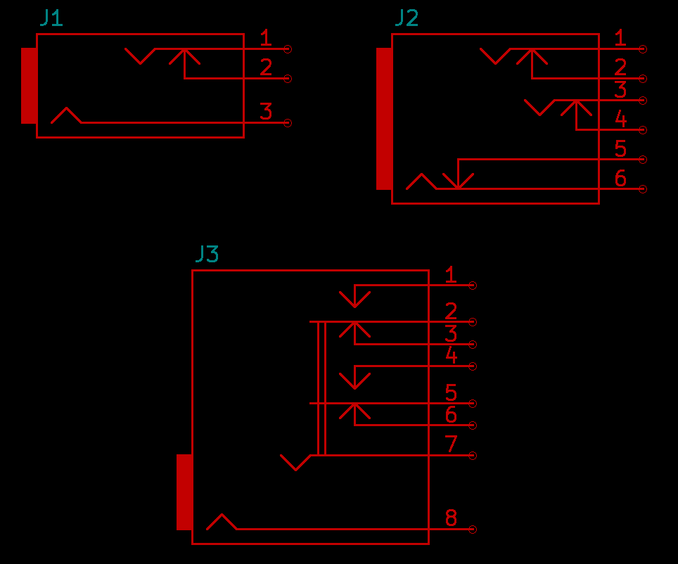
The J1 symbol above is the common Eurorack-style mono mini-jack with a single NC switching contact associated with the tip contact. When there is no plug inserted, pins 1 and 2 are connected to each other. Inserting a plug pushes the movable contacts for pins 1 and 3 outward, breaking the connection between 1 and 2. Pin 1 connects to the tip of the inserted plug, pin 3 connects to the ring, and pin 2 is disconnected. A module would be designed with the circuit input wired to pin 1, and a source for the default signal, meant to be used when the user has not patched in a cable, wired to pin 2.
The switching contact is sometimes called the "ring" contact, but it shouldn't be. The "ring" is properly the additional signal contact in a stereo socket. It connects to a literal ring of metal in the corresponding plug, and in a stereo hookup it usually carries the right-hand channel. The switch contact in the most common kind of mono socket connects instead to the tip contact when there is no plug inserted, and to nothing when there is a plug inserted.
The confusion between tip-switch and ring comes about because switched mono and unswitched stereo sockets look quite similar. They each usually have three connections, and the ring connection on a stereo jack is often in just the place where the switched connection on a mono jack would be. There is further opportunity to be puzzled because (as described below in the section on guitar pedals) there are actually some situations where a true ring contact might also be used for a switching purpose. Nonetheless, a ring contact and a tip-switch contact are two different things, and your circuit will probably not work well if you use one where you needed the other.
At J2 I've drawn a more complicated stereo jack with NC switching contacts on all three conductors. Without a plug inserted, pin 1 connects to pin 2, 3 connects to 4, and 5 to 6. Inserting a plug breaks all those connections; the plug's three conductors connect to the contacts for pins 1, 3, and 5, and the other three pins are disconnected. This kind of jack socket might be used in a studio patch bay, with a stereo or balanced signal and a desire (for better control of grounding and shielding) to completely break the normalled connection when a plug is inserted.
The J3 symbol illustrates a mono jack socket with two isolated pairs of NC (normally closed) and NO (normally open) contacts. The switching logic is basically that of a DPDT switch mechanically linked to the socket. Note the double lines, which indicate a mechanical linkage without an electrical connection. Pins 7 and 8 are the tip and sleeve contacts, and the socket does not make any connection between them and the switching contacts, with or without a plug inserted. Pins 3 and 6 are NC switching contacts. With no plug inserted, pin 2 connects to 3 and pin 5 connects to 6. Pins 1 and 4 are NO contacts, disconnected when no plug is inserted. Inserting a plug into this socket pushes the movable contacts 2 and 5 outward, breaking the connections with pins 3 and 6 and instead connecting 1 to 2 and 4 to 5. Sockets with elaborate built-in switches like this are not manufactured much anymore, and if you could find one newly-made it would be very expensive, but they were at one time used in old manual telephone exchanges, to allow for complicated switching and routing logic activated by the operator plugging cords into a panel.
There are different styles of schematic symbols for jack sockets and their switching contacts in common use. I drew the ones for J2 and J3 above to imitate the style of the J1 symbol; but if you look on the Net you will also find symbols that show the sleeve contact as a rectangle instead of the kinked line I used, or that use triangles or dotted lines instead of a double line to indicate electrically isolated mechanical linkages. The concept is almost universal that the schematic symbol shows how things connect when there is no plug inserted. If the arrow for one contact is drawn touching another contact, then that is an NC contact: normally closed, disconnected by inserting a plug. If the arrow is drawn not touching the other contact, then it is an NO contact: normally open. Inserting a plug is always imagined to result in pushing the movable contacts outward from the centre of the symbol; from that you can infer what will connect to what when the plug goes in. And it is to be understood that the symbol is schematic - it indicates conceptually how the switch operates in terms of which connections are made and broken. The real physical arrangement of contacts may be quite different from how they are laid out on the page, as long as the socket makes and breaks electrical connections according to the logic of its schematic symbol.
Circuits and applications
One common pattern is that a module with several inputs may have them normalled to each other. For example, in the TipTop Z8000, there are a couple of groups of four sequencers where you might often want to drive all the sequencers in the group from a single clock; so each sequencer in the group defaults to take its clock from the previous sequencer's input jack: 2 is normalled to take input from 1, 3 is normalled to take input from 2, and 4 from 3. Plugging a clock into jack 1 will drive them all. Plugging into more than one will split the sequence at each inserted plug; for instance, plugging clocks into jacks 1 and 3 will drive 1 and 2 as one group and 3 and 4 as a separate group.
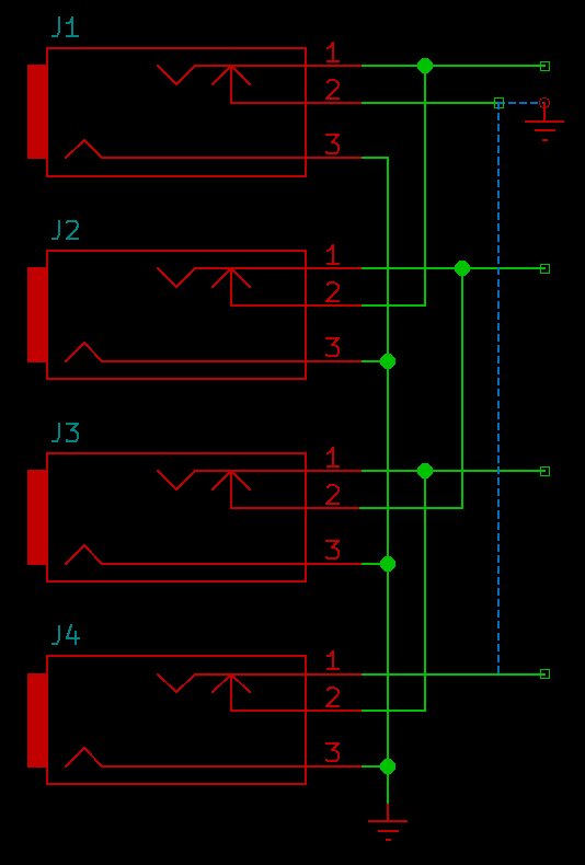
There is an interesting question of what to do at the start of such a cascade: where does J1 take its default input? I have drawn in two possiblities with dotted lines on the schematic. One way would be to just have J1 normalled to 0V. I tested a few modules (from other manufacturers) in my own rack and found that most of them work that way: if you plug into just one jack socket of a multi-way normalled group, then those below or after the plug get the plug's voltage and those above or before it have only 0V input. But another possibility, which I quite like, is to loop it around and have the first jack in the cascade take its normal input from the last. That way, plugging into any jack in the cascade will drive them all; but you can still break the cascade at any point by inserting a second plug. The Octave Switch normalling described at the start of this article is a two-channel example of this kind of circular arrangement.
When a single cable drives several inputs through normalling, the input impedances are effectively connected in parallel, and that can be an issue especially in Eurorack, where impedances are not well standardized. The basic assumption in Eurorack is that the input impedances should be much higher than output impedances. As long as that remains true, it is possible to talk about signals purely in terms of voltage without needing to think too hard about the amount of power that may or may not be behind that voltage. A single Eurorack input's impedance is often quite high; 100kΩ is typical and often taken as a guideline, but that is by no means exact in every case, and a given input's impedance often varies with things like the position of an attenuator knob. An output's impedance is usually (on a powered module...) at most 1kΩ, but often an output circuit that gives effectively zero output impedance. If everybody followed those rules, then putting four or even eight inputs in parallel through normalling or multiples would still keep the effective input impedance well above the effective output impedance.
But the rules are not always followed. Some modules have input impedance significantly lower to begin with, which will be lowered further if those inputs end up in parallel. Unpowered ("passive") modules usually need to have their input and output impedances on the same order of magnitude - so the designer of such a module might aim for input and output to be around 10kΩ. That will be comfortably greater than the output impedance of a powered module, and comfortably less than a single input impedance of a powered module, so the unpowered module can be patched between two well-behaved powered modules. But if other modules are also passive, or driving multiple inputs through normalling, or making exceptions to the usual practice for various reasons, then there can be problems with a passive module trying to fit between them.
If not normalling an input to another input, another common design pattern is to connect it to a constant voltage, especially if the input has an attenuator knob. That way, with a control voltage patched in, the knob controls attentuation of the input voltage, and without a patch, it attenuates the constant voltage.
It's probably a bad idea to connect the normalling contact directly to a nonzero power supply voltage because of the risk of shorts. When someone plugs a cable into the socket, quite often the tip of the plug will hit the tip contact of the socket briefly before that contact bends away from the normalling contact; so for perhaps a few milliseconds, there is a three-way connection formed between the external signal, the normalling voltage, and the circuit input. If the external signal and normalling voltage are both low-impedance, it can create a significant current spike.
People usually don't bother with a series resistor on the normalling contact when normalling a jack to 0V in particular, because the plug tip will usually short into ground for a few milliseconds anyway (through the bushing of the jack socket) on its way in; there's no real way to prevent that, so outputs need to be able to deal with that particular scenario, and it is less likely to be a concern than a short into a nonzero power supply voltage. But if normalling a socket to a constant non-zero voltage, it's usually better to add a series resistor; and in that case, the series resistor should be calculated to produce the desired equivalent voltage in relation to the input circuit's impedance.
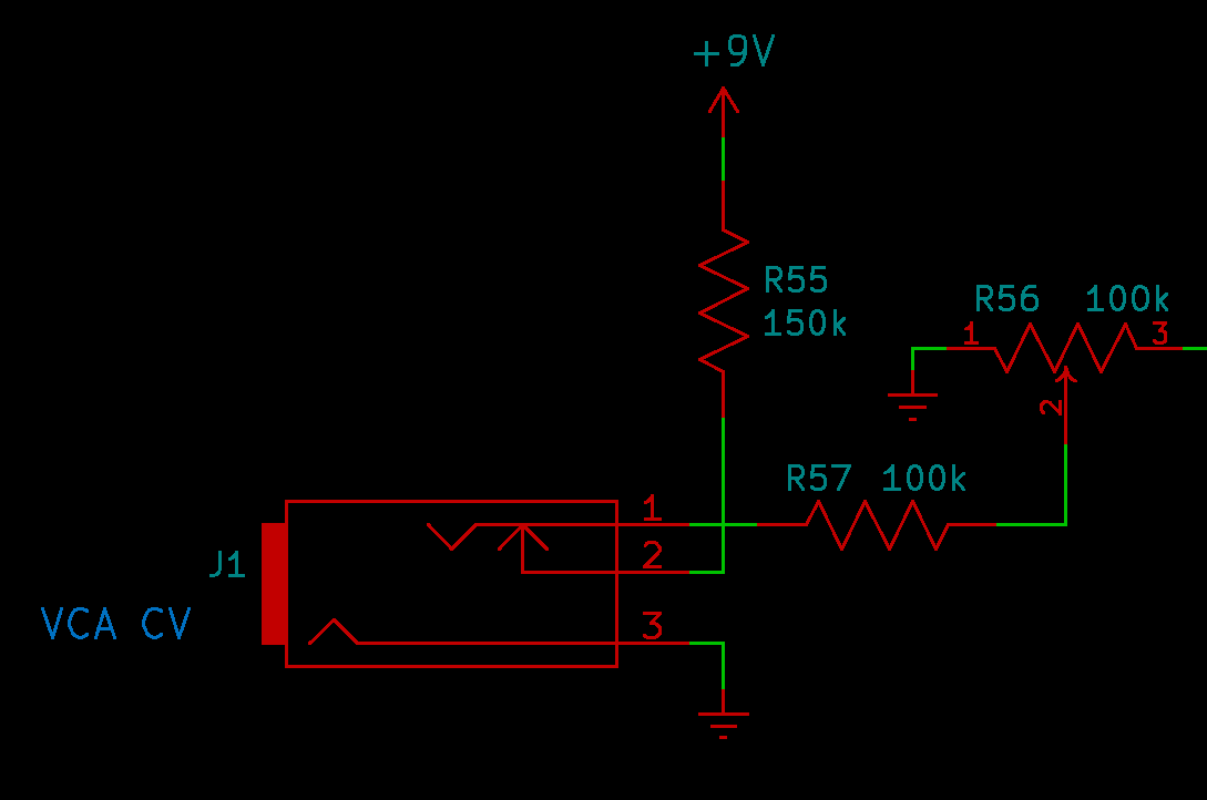
Here's an example from the VCA control input of the Leapfrog VCF. Note that pin 3 of R56 connects not to an op amp virtual ground but to the high-impedance base of a transistor, so with the knob turned to maximum, the impedance from the jack socket to ground is about 200kΩ. Applying 9V through the 150kΩ resistor is then equivalent to applying about 5.14V from an ordinary low-impedance output, by a standard voltage-divider calculation (9V times 200kΩ/350kΩ). The 150kΩ resistor ensures that very little current will flow if an output is briefly shorted into the switching contact during patching.
I've sometimes heard complaints about the common scheme of normalling to constant voltage with an attenuation knob, along the lines of "the knob shouldn't change its function from attenuation to offset depending on whether there is a cable plugged in; having a knob change function is confusing." Such complaints come from a misunderstanding of what the knob's function actually is. The knob is always an attenuator in this circuit; its function does not change. What changes is the input to the attenuator - that comes from a plugged-in cable if there is one, or a constant voltage if not, and the switching between those two possibilities is done by the switching contact in the jack socket.
It's not always clear what someone with this complaint thinks ought to be done instead; possibly they want the default voltage (whether achieved with a switching contact or some other means) to be zero, so the attenuation knob will do nothing when there is no cable plugged in. But having a knob go dead can be a usability problem. Users unfamiliar with a module are prone to grabbing knobs, twisting them, and then complaining if nothing happens. Normalling the socket to a constant nonzero voltage, so that the attenuation knob can do something useful even without a cable, seems like a clear improvement over just having the knob's effect be imperceptible when there is no cable attached. Users who want zero output from the attenuator are still free to turn the knob down to zero.
It may be that the real issue is, users would like to have separate offset knobs which always apply an internally-generated voltage, in addition to the attenuation knobs that work on external voltages. That clearly provides more options, and with an extra knob for offset, having the default input to the attenuator knob be zero makes more sense. That's fine, but it has to be balanced against the cost of adding another knob to the module, in both money and panel space. If it means an extra $20 added to the module's retail price and an extra 1HP added to the module width - which I figure are reasonable estimates of what another knob adds - then many users will not prefer the module with the extra knob. I figure, if you are going to complain about not having a separate offset knob, then you're never allowed to post a "list of SMALL modules 2025" forum thread again.
What if there is no useful default value for an input? Should the switching contact be left unconnected in that case? Should it go to 0V?
She came naturally by her confused and groundless fears, for her own mother lived the latter years of her life in the horrible suspicion that electricity was dripping invisibly all over the house. It leaked, she contended, out of empty sockets if the wall switch had been left on. She would go around screwing in bulbs, and if they lighted up she would hastily and fearfully turn off the wall switch and go back to her Pearson's or Everybody's, happy in the satisfaction that she had stopped not only a costly but a dangerous leakage. Nothing could ever clear this up for her.
- James Thurber, My Life and Hard Times
The story circulates among synthesizer users that an input connected to nothing at all will "pick up noise" by a physical effect similar to how a radio antenna works, and so if one is not deliberately normalling an input to something other than 0V, then it should always be normalled to 0V. That story is not literally accurate. Radio antennas, with some few exceptions not relevant here, need to be on the same order of magnitude in size as the waves they will recieve. They will not pick up any other signals. An open-circuited input jack certainly cannot pick up any audio-frequency noise; the waves in question, and therefore the wire that could receive them, would be many kilometres long. The PCB trace and other wiring between a Eurorack front-panel jack and the circuitry it connects to are usually only about 1cm to 10cm long, which corresponds to a frequency in the range of about 3-30GHz; frequencies on that order of magnitude are the only ones it can pick up. If you have enough microwave energy floating around your environment for an audio input circuit to be affected by receiving gigahertz-range signals through a disconnected trace like an antenna, then you already have serious interference problems through other routes anyway. Using the switching contact to short an input trace to zero when not in use isn't going to save you from that.
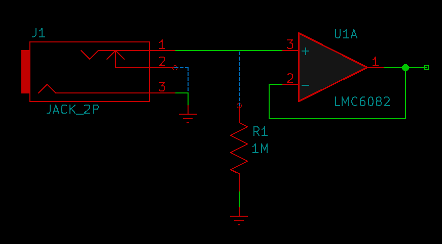
However, there may be input circuits that respond poorly to having nothing connected at all because they don't like the high DC impedance of an open circuit, and in that case, shorting the input to ground through the switching contact might be a good idea. At least, it will seldom hurt anything to do so. For example, if the jack socket connects directly to the input of an op amp IC and nothing else, then the op amp may behave unpredictably when there is nothing connected. Some op amps given no input at all behave as if the disconnected pin were a high voltage (leading to spikes on the output when things are patched and unpatched); others behave as if the voltage were low; and this may vary with the individual op amp chip. I drew a CMOS op amp in this schematic example, as one that might be especially sensitive to such issues.
It might be best to connect the input pin to ground with a high resistance in this case, to provide a controlled impedance regardless of plug insertion, but there could be reasons not to, and at least normalling the input to zero would be better than nothing. Static electricity is another possible issue with disconnected inputs: probably not a problem while the module is installed in a rack, but if the input is not normalled to zero and the user handles the module with staticky hands while installing it, then an IC pin could receive a damaging shock. All in all, normalling inputs to zero when there's nothing else to normal them to is probably a good idea, even though that is not because they might "pick up noise."
Normalling can work on output sockets as well as inputs. You wouldn't want to connect the switching contact of an output to constant voltage, because that would short out the output whenever there is no plug inserted. Connecting it directly to another output would be a problem for similar reasons. But the switching contact in an output socket can become input for some other part of the circuit, overridden when there is a plug inserted. One very common pattern (seen, for instance, in the Intellijel Linix) is that you might have several outputs with individual jack sockets, and a "mix" output that is a mixture of all the outputs not individually patched. Patch in a cable to remove an output from the mix and handle it individually.
Normalling in studio patch bays
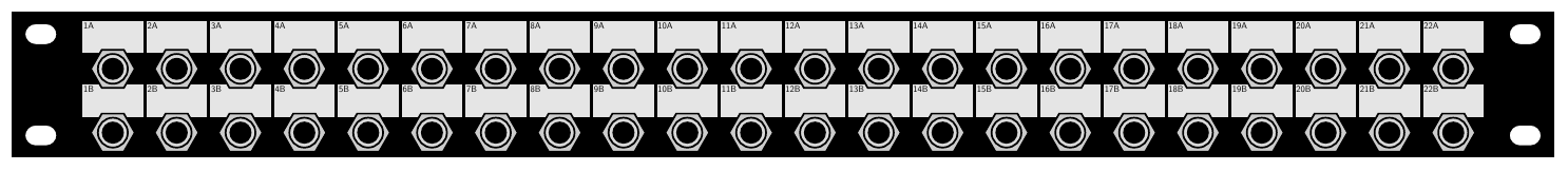
A patch bay for a 19" studio rack usually looks something like this, with two horizontal rows of jack sockets. This is a front view; each socket will also have a connection on the back panel. Sometimes the sockets themselves will be keystone type, with the possibility of swapping them out for different connector styles.
When you're setting up your studio, you typically hook up the outputs of your different pieces of equipment to the sockets in the top row, from behind. You hook up the inputs to the sockets in the bottom row, from behind; and you do it in such a way that each input is right below the output that will normally drive it. By default, with nothing connected to the front, all the top-row outputs connect to the bottom-row inputs. For example, you might have mic preamps and a synthesizer normally connected to the inputs of a computer audio interface, with an effects unit off to the side.
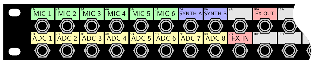
When you want to make other connections, you add patch cables to override the defaults. For example, you might want to insert your effects unit between one of the mics and the computer.
It is assumed that the jack sockets in the patch bay have switching contacts, much like the Eurorack switching contacts, so that inserting a cable overrides the default connections.
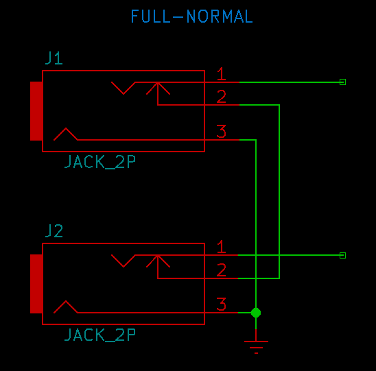
In more detail: pairs of jacks in a studio patch bay are usually connected together, or not, in one of three ways: full-normal, half-normal, or non-normal (sometimes also called "de-normal"). Some patch bays are permanently wired for one of these on all channels, but most will offer some more or less convenient way of selecting a normalling option for each channel. When you set up your patch bay and choose what each jack will do by connecting things to the back, you also choose the normalling.
Full-normal means that the connection between the two jacks uses the switching contact on both jacks. If you plug into either of them, the switch in that jack will open and the connection will be broken.
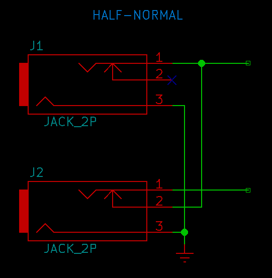
Half-normal means the connection goes through the switching contact on the lower (input) jack socket but it uses the unswitched contact on the upper (output) jack. If you plug into the upper jack, it is like a modular multiple. You are connecting the cable to the output while leaving the output also connected to the input. You might choose to make a channel half-normalled if you think you will often want a second copy of the output's signal while leaving the normal connection in place. If you want to break the half-normal connection after all, you can do it by patching into the lower jack. Half-normalling offers more possible options from the front panel, but it may be inconvenient if you often want to break the connection and have nothing driving the lower-row input, because in that case you need either a dummy plug, or a cable with a disconnected end hanging out.
Non-normal means that by default there is no connection between the top and bottom sockets at all. They are independent, and connected to nothing until you add a patch cable. Not every studio patch bay offers non-normal as an option, but it might be appropriate if you want a piece of equipment like an effects unit to be available in the bay without planning to use it all the time. Non-normal is also the expected configuration for other kinds of patch bays (like Ethernet computer network patch bays), where switched sockets may not exist.
I drew my circuit diagrams above with unbalanced TS mono connections and all the sleeves connected together unconditionally, as might typically happen in cost-conscious Eurorack design. Patch bays can also be made with TRS connectors and switching contacts on both tip and ring, to handle stereo or balanced signals. Whether to connect all the sleeves together; connect them only in pairs; or not connect them at all, is a question with complicated implications beyond the scope of this article. It depends on the studio's overall grounding and shielding strategy. Connecting them all together is what Eurorack usually does, and is one of the things that professionals from other disciplines like to sneer at. Having switching contacts on the sleeves too, and switching them the same as the tips and rings, might be ideal. But sockets with three switching contacts, capable of doing it, are uncommon and therefore expensive.
I've heard from people accustomed to studio patch bays who hope for Eurorack modules to work just like studio patch bays - with extra connectors on the backs of the modules to set up a default signal path more or less permanently during installation. That is probably a vain hope. There are a few pairs of modules from the same manufacturer designed to allow connection to each other, specifically - for instance, Intellijel's Mutamix and Linix have "link" headers on the back, through which the outputs of the Linix can become the default inputs of the Mutamix. I don't know of any Eurorack modules with general-purpose normalling connectors on the back like a patch bay, however, and it would be difficult to implement well. In order for it to be useful, most if not all the modules in the rack would need to have the rear connectors. And given that connectors are some of the most expensive individual parts in a Eurorack module, and they might need additional circuitry like extra buffers, providing this feature would be expected to significantly increase the price of each module.
You would need at least an extra 60mm of space behind the modules to have space back there for comfortably plugging in standard Eurorack patch cables; less if the back connections used some other and more compact type of connector, but then standardization would be even more difficult and improbable. Studio racks usually have plenty of space at the back because they are designed with the expectation of people making many connections to the backs of equipment, but Eurorack cases, despite being derived from the studio rack standard, are often much shallower. And it's simply a fact that setting up one standard patch that will only relatively rarely be overridden, is not such a useful feature anyway. People want to do that in studio installations and they much less often really want to do it with a modular synthesizer.
So if you really want configurable normalling with connections at the back like a studio patch bay, barring the idea of DIYing your own custom synthesizer format, the best thing is to actually use a studio patch bay. You can get them with Eurorack-style mini-jacks, and it would make a lot of sense to mount Eurorack modules in a 19" rack frame like the Doepfer A-100G6 with a standard 19" rack-mount patch bay immediately above or below the Eurorack frame. There would still be a question of how to get Eurorack signals to and from the patch bay. It could involve plugging them directly into the front, or perhaps leaving a space and running them through the gap to the back of the patch bay inside the rack, leaving the front to accept cables in exactly the configuration of any other patch bay. Perhaps other channels could also be used for non-Eurorack studio equipment.
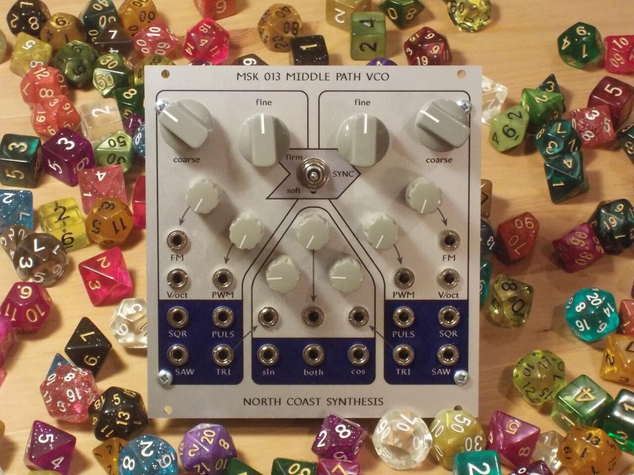
Eurorack does have a standardized, though limited, feature for default patching by means of the CV and gate lines of the Eurorack bus. Doepfer defined the 16-pin power connector to include connections for default pitch and gate CV, and some modules will send and receive signals through those when this behaviour is not overridden, that is, as a normal connection. Among North Coast modules, the Middle Path VCO connects to the pitch CV by default (overridden by an inserted patch cable or a permanent build option). The Gracious Host connects to both pitch and gate CV, depending on jumper configuration. Plug a Gracious Host and a Middle Path into the same bus without any other connections, and the Gracious Host will automatically control the Middle Path's pitch. You can override that temporarily by plugging in a patch cable, or semi-permanently by changing the jumpers. Some modules from other manufacturers are also compatible with the Doepfer-style analog bus standard and can communicate with these modules by default.
On the other hand, some manufacturers have observed the thin adoption of Doepfer-style analog bus signals, and have repurposed those wires of the Eurorack bus for digital communication - often under the name "sync bus," but that is not the name of a single standard. Different manufacturers have created incompatible digital "sync bus" systems. As long as there is only one protocol in use on a given bus board, it should work fine; but they may conflict if mixed.
Normalling without switches
In the Eurorack world we use 3.5mm mini-jack connectors for patching, traditionally called 1/8" size although the well-actually crowd will be happy to inform you that the connectors are really a little bit bigger than exactly one eighth of one inch. My own view is that it's like calling a two-by-four a two-by-four, or even like calling a Eurorack module 3U; nominal sizes don't need to represent an exact dimension measurement. Anyway, whatever you call their size, the sockets for these connectors often have switching contacts, and normalling by means of those contacts is a well-accepted and common practice.
What about banana sockets, as commonly used in some other synthesizer formats? In principle, one could design and manufacture a banana socket with a switching contact; but such sockets are not in common use, and they would probably be expensive speciality parts. The most popular styles of banana socket have only a single connection for the signal conductor, without a switch or even a ground. Most modules designed for banana formats just don't have normalling features. When DIYers occasionally want to adapt a Eurorack design to a Serge or Buchla format, there's a question of how, or whether, to replace the normalling function of a switched socket without actually using a switched socket.
One way to do it is by connecting the "default" signal to the socket and to the circuit input through a high resistance, like 1MΩ. This method depends on the circuit input having a very high impedance (like the input of a FET-based op amp) and the output that might be patched in having a much lower impedance.
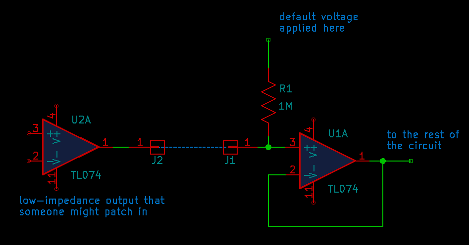
When there is nothing patched into the socket, the input sees only the voltage on the other side of the 1MΩ resistor. When there is an output from another module patched into the socket, the other module and the default signal are both driving the input, and the input sees a weighted average of the two. If the output's impedance is low, then it has much more weight, and the input basically sees only the output, not the default voltage.
The resistor technique often works well, but the restrictions on impedance can become a problem. Not every downstream circuit will have a high input impedance. Not every output that might be patched in will reliably have a low impedance; and the fact that the input in this case presents a non-zero open-circuit voltage to the output, may confuse the output. Some outputs designed to produce logic levels (triggers or gates) do not really act as high and low voltage drivers; instead, they produce a voltage with some power behind it (low impedance) in one state and they effectively disconnect (high impedance) in the other state. I showed an example output circuit with a series diode in my design mistakes article.
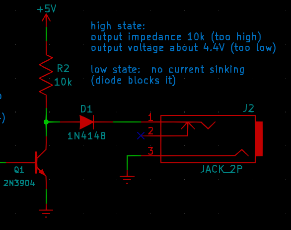
Designers sometimes do that on purpose after careful thought, especially on trigger outputs, so that you can get an AND or OR function "for free" by patching two or more such outputs together into a multiple. Ordinary outputs with low impedance in both states would conflict in such a patch; these won't. That's fine as far as it goes, but such a design may have unexpected consequences when combined with the "fake normalling using a resistor" input configuration. If you have an input that defaults to high by means of a resistor, and you patch in an output that is high-impedance when in its low state, then the input may end up just being high all the time and never recognizing a low state at all. Something similar can happen in the opposite direction with outputs that are high-impedance in the high state.
A module with a digital microcontroller in it can sense cables less intrusively by putting a GPIO pin on the other side of a somewhat lower-valued resistor. It is assumed that the microcontroller also has access to the signal voltage, for instance through an ADC somewhere downstream. Voltage protection for the microcontroller pin is not shown in this schematic fragment but would be important in practice.
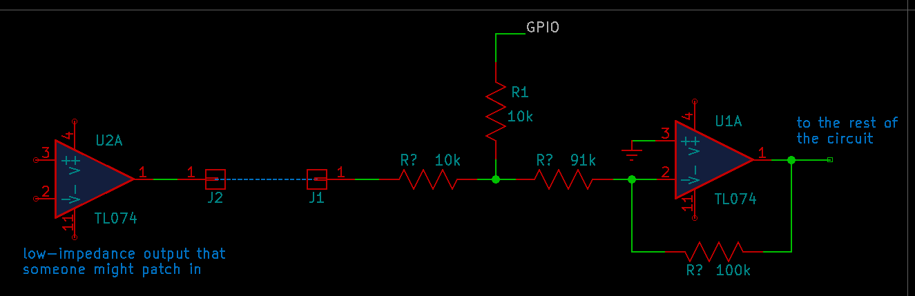
Most of the time, the microcontroller keeps its GPIO pin in high-impedance mode, effectively disconnected from the circuit. Once in a while, it activates the pin, sends a pseudorandom signal into it, and looks for that signal in the input. By measuring the strength of the pseudorandom signal seen in the input, it can get an estimate of the impedance of whatever is patched in; infinite if nothing patched in, less if it's a cable driven by an output. Except during the measurement, there is no impact on the signal going through the connection, although some care would have to be taken to make sure that the voltage ranges at the input socket and the microcontroller pin are compatible.
Mutable Instruments uses something similar to that, referred to in the schematics and source code as the "normalization probe," on several modules - but the Mutable design is for Eurorack and connects the microcontroller output to the switching contact, so there is no impact on the signal with a plug inserted. Doing it with a non-switched socket is less elegant than the Mutable design, but may still be useful because there is a lot of opportunity for the microcontroller firmware to work around any undesirable effects. This technique can work with outputs that are relatively high-impedance, or with inputs that are lower-impedance than would be required by the always-on resistor scheme.
In the case of output normalization, where the module is expected to do something different depending on whether an external cable has been connected to an output socket, there is some possibility of measuring how much current the output is providing. Consider the following circuit. I've included stability-encouraging components (C1 and R2) that might typically be used in a real output circuit, even though they are not essential to the current-sensing scheme.
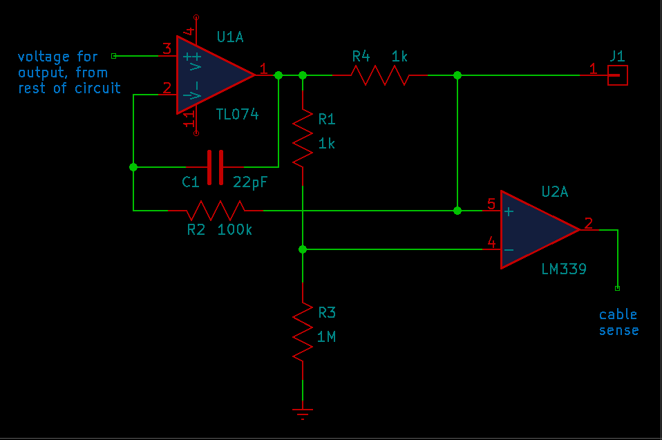
That is basically the same as the plain resistor technique I described for inputs, with a separate comparator to detect the cable instead of the normalling voltage as a default for an existing input. In this circuit, a voltage divider from the op amp output to ground provides a reference voltage a few millivolts less than the op amp output. With nothing attached to the output socket, the output socket floats at the op amp output voltage - higher than the reference. But if the output socket is patched to another module's input, it will draw current through R4, probably toward ground. That creates a voltage drop across R4, and the op amp will compensate by raising its own output voltage to keep the output socket equal to the op amp positive input. If the external input has a sufficiently low impedance, the voltage drop across R4 will be greater than that across R1, the reference will be greater than the output socket voltage, and the comparator will change states.
This circuit fails if the external input's impedance is on the order of or greater than the 1MΩ resistor R3 - which can be increased if necessary, but cannot usefully be increased beyond the finite impedance of the comparator inputs. The circuit also fails if the external input's open-circuit voltage (usually but not always zero) is not less than the voltage the output was trying to produce; so the circuit as drawn is at least unlikely to work for zero or negative output voltages, and it may also fail in other cases. It might fail, in particular, when connected to an input that was also trying to fake normalling with a resistor to a nonzero voltage - so not too many banana modules can safely use these techniques. The circuit might be improved to detect more cases by adding a second comparator with the opposite polarity, but doing so adds complexity and would not allow reliable cable detection in every case.
Guitar pedal power switching
There's a specific thing you often see in guitar pedal circuits; it looks like this. Guitar pedals normally take mono inputs; but that is a stereo jack socket symbol! What's going on?
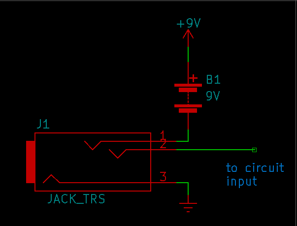
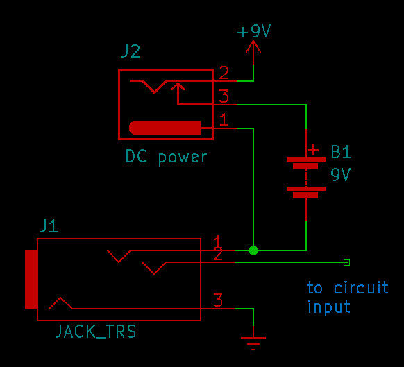
The concept is that the pedal would traditionally be powered by a 9V battery. In real life, many users will plug in a 9V power supply instead, but the designer still wants it to be possible to use a battery. They don't want to give the pedal an on/off switch - not only because they don't want to pay for the part, but also because the user shouldn't need to worry about switching it on and off. It really sucks to try to play your guitar through a pedal, have it not work, and then remember that you have to stop and turn it on first; it's even worse to remember that you didn't turn it off last time and now the battery is dead. Murphy's Law guarantees these things will happen at the most inconvenient times, and guitarists do not enjoy such surprises in the middle of or immediately before a performance. So the designer wants to make the pedal automatically turn on when the user inserts a plug, and automatically turn off when the plug is removed. It means fewer complaints from customers, and more future sales.
Ideally, you might use a jack socket with a switching contact that goes the other way. The standard Eurorack switching contact is normally closed (NC); it connects when there is no plug inserted and disconnects when there is a plug inserted. To control the power connection on a guitar pedal, you really want a normally open (NO) connection: connected when there is a plug inserted, and disconnected without a plug. But jack sockets with built-in NO switches, although they exist, are uncommon, bulky, and expensive. So the cliche guitar-pedal design uses the ring connection of a stereo jack socket to fake an NO switch.
The stereo socket is a TRS socket: tip, ring, and sleeve. In its standard use for a stereo signal, the tip would be left, the ring would be right, and the sleeve would be ground. But in a pedal, the guitar plug that plugs into this socket is expected to be a TS plug: just tip and sleeve without a ring. With a plug inserted, the socket's ring contact will touch part of the sleeve on the plug, and it will be shorted to the ground voltage on the sleeve contact. Without a plug, the ring contact will be unconnected. That gives us our desired normally open switch logic, subject to the restriction that the switch can only go to ground.
Instead of switching the positive side of the battery, as might be conventional in other battery-powered circuits, the pedal designer leaves the positive side connected to the circuit all the time and switches the other side. The negative side of the battery is wired only to the socket's ring contact. Without a plug, the battery floats and does not discharge. With a plug, the battery negative connects to the circuit ground (the 0V, if we must) through the ring contact, the plug sleeve, and then the sleeve contact, and the circuit operates.
A small gotcha is that it only works with an unbalanced mono, TS, plug. Plug in a TRS plug (stereo or balanced mono), and the battery will be connected to whatever is on the other end of the ring wire, instead of powering the pedal. But guitar pedals so often have this power arrangement that users usually know they should not do that.
Pedal designers usually also want to allow for the possibility of plugging in a DC power supply, which if present should override the battery. The common guitar pedal DC power connector has a negative tip and an NC switching contact for the positive sleeve, much like the mini-jack switching contact, so they can wire that to the positive lead of the battery as shown below. With a DC power plug, the circuit uses the DC power supply; without one, it uses the battery; and either way, it is switched off until the user inserts a TS plug for the input.
To summarize, I've gone through what normalling is; how it is accomplished with switching contacts; and some common ways it is used. I've described some of the less obvious implications of normalling, and discussed its use with studio patch bays in particular; how it can be accomplished in systems without switched jack sockets; and the way guitar pedals commonly use jack sockets for switching power.
◀ PREV MSK 014 release || A fractal sequencer toy NEXT ▶