Designing for adjustment
2019-09-15 design electronics
Testing and adjustment are often underestimated in DIY circuit design. It's all very well to choose exactly the right topology and component values for a circuit; but even with a perfect design on paper or in the simulator, how does one get from there to a physical construction that correctly realizes that design?
Software developers have elaborate procedures for "testing" and "design for testability," intended to make sure that no buggy code gets shipped to end users. The idea that code should not only be right, but it should be possible to test whether it is right, is supposed to be built in right from the start. Those procedures may or may not work well; but in the software case it's a relatively easy problem because only the design needs to be tested anyway. If the code is good, it will be good for everybody because it's the same code for everybody. With hardware, we have the additional issue that the design needs to be manufactured, and problems can be introduced at that stage: even with a perfect design, there can be build errors or defective components, and even with a correct build and good components, there can be natural variation among the individual components, requiring adjustments and trimming for each individual unit.
Testing, to find bad units, and adjustment, to get a good unit working as it should, are significant costs in electronics manufacturing. As devices come off the line, it's necessary to test them to make sure they're good, and possibly to adjust them, to take into account component variations. Related terms include "calibration" (which properly only applies to measuring devices - making sure they measure quantities accurately) and "alignment" (a specific adjustment relevant to superheterodyne radio equipment, that makes sure all the different stages are tuned to properly-matching frequencies).
The Leapfrog VCF in particular has an especially complicated adjustment procedure, with thirteen different trimmers that all need to be set correctly for optimal performance. I probably spend more time adjusting Leapfrogs than building them, and it's why I charge so much extra for a built Leapfrog over the price of a kit. Trimmers are expensive, but in a commercial environment the labour cost to adjust them is even more expensive, so it's important for circuit designers to think through the adjustment procedures. That's what I'd like to look at in this article. Right now I'm writing mostly from the point of view of adjustment - that is, getting a good unit working as it should. Testing, to find out whether a unit is good or not, and troubleshooting, to figure out what's wrong with a bad unit and how to fix it, are important and closely related but not exactly the same activities.
What needs adjustment and why?
The usual reason a circuit needs to be adjusted is to take into account component variation. Simple passive components have a tolerance range. With a 1% resistor, the manufacturer only promises that the resistance will be somewhere from 0.99 to 1.01 times the nominal value specified by the colour code. We routinely use 1% resistors today, but they were not always available cheaply; at one time, 5% was the usual standard. Other components, capacitors in particular, are often only available in wider tolerances like 5% or 10%. The design of a circuit is often such that the tolerances of multiple components are compounded: for instance, a voltage divider built from 1% resistors may have its output only accurate to within 2% of the desired value because it depends on both resistors.
And we often need some parameter to be controlled to much better than the tolerance of the components. For instance, human ears can detect pitch quite accurately. If a V/octave pitch control voltage is out by 1%, that is 12 cents per octave, and will be noticeable over the range of just a few octaves even in a monophonic synth. If the synth plays two notes at once and there is 1% frequency or pitch-CV difference between them, it will be noticeable even within a single octave. When the CV has to go through a couple of op amp stages with two or three components in each one that all could be out by 1%, it will hit 10% possible error quickly, and it's clear that something needs to be done to trim out the component variation.
Passive components are not the only source of variation. Individual examples of bipolar transistors may have wide variation in reverse saturation current (which determines VBE and is relevant to exponential converters in particular), in current gain (important in some amplifier circuits), and in noise output during breakdown (for transistors used as noise sources). Discrete JFETs, if you can find them at all anymore, are quite variable in their cutoff voltage. It's because of those issues that people spend time matching or selecting individual transistors to use in construction; it's not always enough to just get the right part number.
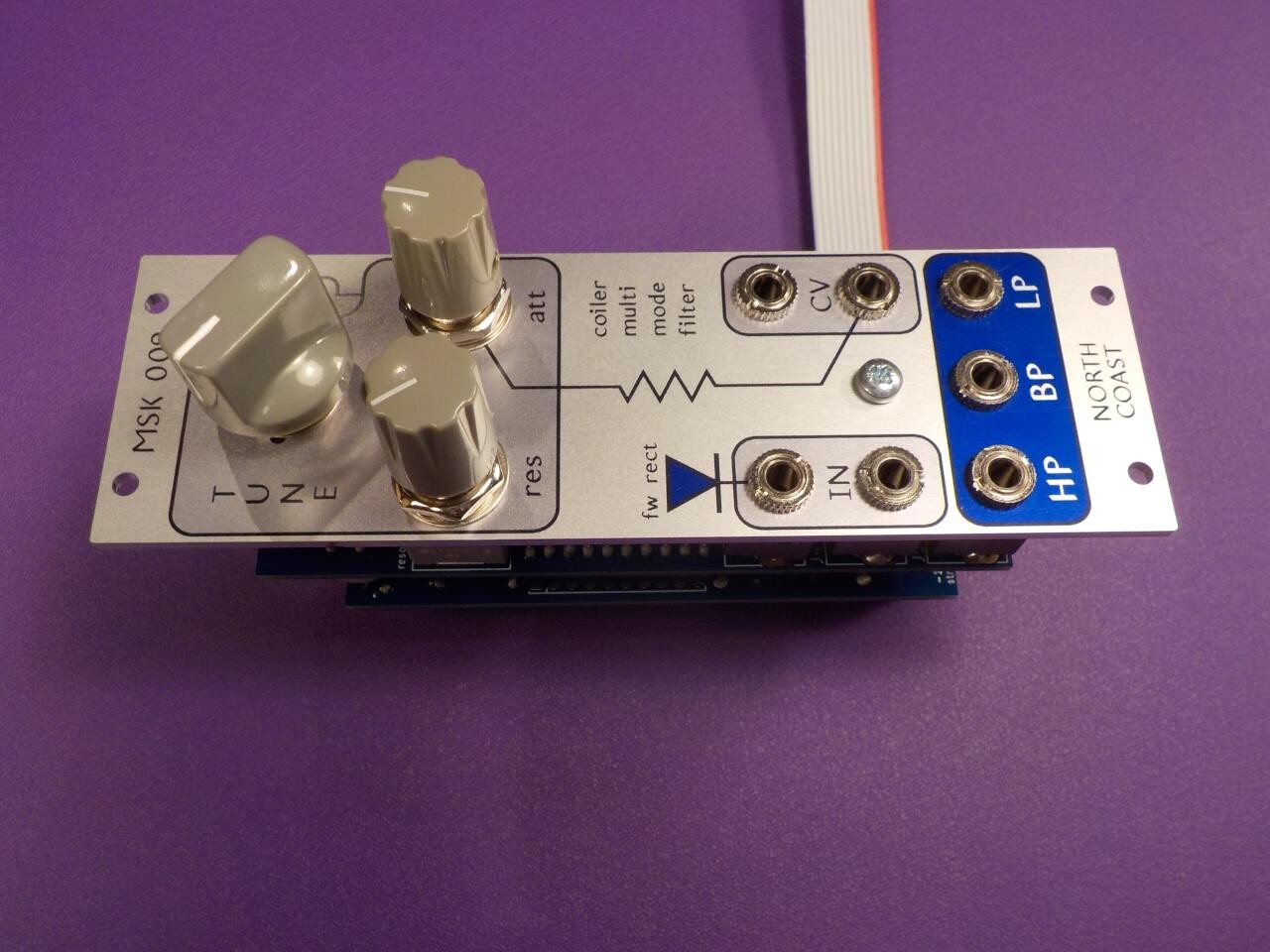
Analog ICs like op amps benefit from having all their transistors on the same chip, so the matching in an IC is usually better than would be possible with discrete components (one reason "discrete op amps" are usually a bad idea). But there can still be mismatches which lead to stuff like input offsets. Most of the adjustment for the Coiler VCF is intended to compensate for variations in the op amp and OTA chips; although the inductors are also badly behaved, their variation is mostly in frequency and distortion characteristics, and left uncompensated as an aesthetic decision.
Beyond the variation in components, there can be a need for some kind of adjustment that is in the nature of customization. For instance, it's possible to optionally cut some traces and add jumpers during a VC Octave Switch DIY build to choose whether each channel will add or subtract voltages; the Fixed Sine Bank can be built in different frequency variations by rearranging the components; and although I'm not currently selling any like this, some digital modules have a programming step for loading the firmware, possibly including per-module serial numbers or a choice of different firmware options for different users. If anyone remembers ISA expansion boards for PCs Back In The Day, those usually had DIP switches that needed to be adjusted to give different boards non-conflicting IRQ and port numbers when used in the same computer. Something similar was needed for SCSI disk drives.
What doesn't need adjustment?
Even though I gave some examples of digital circuits needing adjustment too, in general the biggest adjustment issues are with analog circuits because there tend to be more component parameters that affect circuit operation in an analog circuit. Nobody cares whether a digital high level is 3.30, 3.27, or 3.33 volts; but that is a ±1% variation and could easily matter in an analog circuit. Digital and digitally-controlled analog circuits also have the advantage that they may be able to adjust themselves with a special feature in the firmware: maybe just press a button combination, or feed in a standardized reference signal, and then let the circuit run its procedure for a few seconds, save the results in non-volatile memory, and do any required compensation for component variations in software from then on.
For a pure analog circuit, it may be possible to avoid a need for adjustment by using narrow-tolerance components that are expected to be right already. That was part of my strategy in designing the Dual VC Octave Switch: it has three trimmers primarily intended to compensate for variation in the op amp chips and switching diodes, but the variation in the gain-setting resistors is limited by simply using 0.1% tolerance resistors which will be very close to the desired values even without any adjustment. There's a tradeoff of the increased parts cost of the higher-precision resistors, against the cost of having more trimmers and adjusting them.
When multiple sources of error interact with each other, it may be possible to combine them into a single adjustment. For instance, every op amp can introduce a DC offset, but if there are three of them in a row, maybe the offset at the output will be just the sum of all of them and we can trim it out in only one place. Even if the interaction is not exact - for instance, if on analysis there are found to be some higher-order terms as well, so it's not always just the sum - it may be that a single adjustment can get us close enough that the remaining error doesn't matter. Something like that came up in the Leapfrog VCF, where the big feedback loop around the filter core involves six OTAs and seven op amps, all of which can have their own offsets which interact in a complicated way through the (also variable) voltage-divider ratios on the many shorter feedback paths, but I was able to get the number of voltage-offset adjustments down to two with still acceptable overall performance by ignoring most of the higher-order terms.
Sometimes the topology of a circuit can be chosen to make some component variations irrelevant and adjustment unnecessary, or at least easier. That is one of the reasons we use op amps at all: it doesn't matter exactly how much gain an op amp has (nor, therefore, any of the gain-related parameters of the transistors in the op amp) as long as it's enough. Op amp circuits are usually designed on the assumption that the op amp has a very high gain reduced by negative feedback. The externally-visible gain of the overall circuit is not determined by the op amp itself but by the resistor ratios in the feedback loop, and those are easier to control. Similarly, if we can throw a capacitor into a signal path to block a DC offset, then we no longer care just what the value of that DC offset might have been.
Although my Leapfrog VCF is intended to receive significant adjustment for optimal performance, one reason for using leapfrog-topology filters in general is that they are relatively insensitive to component variation. As compared to other topologies for a five-pole active analogue filter, the shape of the response curve changes less in a leapfrog topology for a given amount of variation in one of the frequency-determining components. Determining that required some fairly deep calculus (which I did not do myself; it's just a known property of this class of filter designs) but it's a useful thing to know about. One of its consequences is that DIY Leapfrog builders can get away with doing only the relatively easy "pre-adjustment" with an ohmmeter and skipping the more elaborate "full adjustment" which requires an oscilloscope, and the result will still be pretty close to the intended filter curve. With careful analysis or simulation, it's often possible to do something similar with other kinds of circuits: choose a topology or set of parameters that makes component variation have as little effect as possible.
Test points
Doing an adjustment usually means measuring some property of the circuit, such as a voltage, and changing the setting of something like a trim pot to bring the measurement to the desired value. It's worth giving some thought to exactly where that measurement will be taken.
Sometimes it's convenient to just plug into one of the circuit's outputs. I often use a simple adapter made by plugging a patch cable into a spare 3.5mm jack and attaching my multimeter's clip leads to the legs of the jack; then I can easily measure the voltage on a module output by plugging in the other end to whichever output jack I want to test. For grounding a multimeter or scope, I often use an alligator clip to the end of a mounting screw or standoff. That only works if the module connects its 0V reference to the mounting hardware, which is not a universal practice because it's not always a good idea electrically, but it's appropriate for my Eurorack designs.
It's also quite common for the adjustment procedure to require looking at some kind of internal signal not directly visible at the outputs, and then it may be a little trickier to get access to the right signal. Sometimes a multimeter's leads can be clipped onto the legs of a through-hole component; but on high-density and surface-mount boards it can be difficult to poke around with sharp probes and be sure of hitting the right signal. In a multi-board module there can also be important things that are just physically buried in the interior of the construction, not easy to get at.
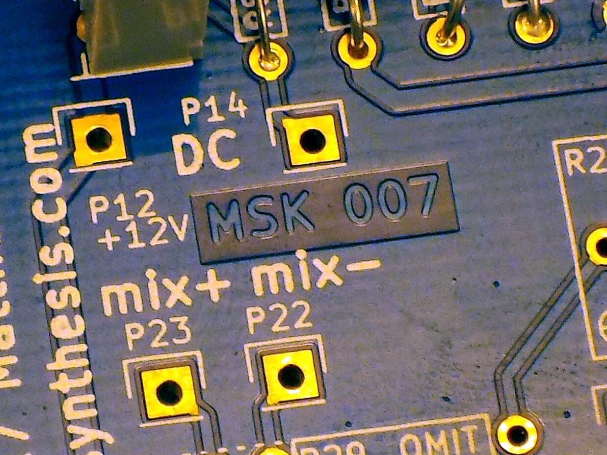
So it often makes sense to design test points into the boards. I usually do it by adding something to the schematic and PCB designs that I tell the EDA software will be a single-pin header connector; then I leave that hole on the board unpopulated. The result is a nice little square pad with a hole in the middle and a silkscreen marking around it - easy to see, and a good target for a scope or multimeter probe tip. In a pinch I can even hook a chunk of wire through one of these and use a clip lead for a connection that doesn't need to be held in place by hand. The location of the test points becomes part of the PCB layout process: if necessary, I can run the test points out on traces of their own to physcially accessible locations even if the main traces for those signals are buried somewhere.
Sometimes, especially if there is room to spare on the board, I'll add in a few extra test points for important signals even if I'm not expecting to use those in particular for the standard adjustment procedure. Having the extras can be helpful in troubleshooting, and it provides some flexibility for possible changes to the adjustment procedure.
Isolating sections
Large circuits usually include a lot of complicated connections, and those connections make trouble for adjustment because they cause interactions among adjustments and circuit sections. If two sections are closely connected to each other, it may be difficult to adjust either one properly as long as the other is out of adjustment, because they affect each other so much; and then it's hard to know where to start. Even within a section, feedback loops in particular (essentially, an adjustment interacting with itself) can make it hard to accurately measure the state of a circuit parameter. And series/parallel effects mean that the value of a parameter like resistance measured across a single component is not the value of just that component, but rather the entire circuit as measured between those points. It may be necessary to calculate a target for the measurement that is not actually equal to the target value of the component itself.
For all these reasons it can be desirable to simplify the circuit just for testing purposes. Break the connections that cause trouble, make the adjustments, and then put the circuit back together into the form in which it will be used. The concept is similar to what the software people call "unit testing."
In one of my initial designs for the Leapfrog VCF, I planned to include a bank of DIP switches and route all the connections among the integrators through those, making it possible to break the feedback loops and adjust each integrator in isolation.
At the time, I was only planning to build the module for myself and release the plans for other hobbyists. It's just as well that I scrapped the DIP switch plan at an early stage, because it would have been a huge mess in a commercial manufacturing situation. Similar concerns applied to the variable-temperature-coefficient compensation I designed into an early experimental multi-oscillator module (which never became a commercial product). Having to actually heat and cool a module to different temperatures to adjust it would drive the price far above anything I could realistically sell. In the current Leapfrog design, I'm doing something a little trickier that still allows for some isolation among adjustments, without adding any extra parts.
The basic issue is that there are variable resistances controlling the integrator time constants and the mixing ratios for the output mixer, and each of these is connected to a bunch of other resistances so that measuring just across the variable part will give a value that also depends on the other resistances. Where in the initial design I used switches to isolate each variable resistance so it could be tested by itself, in the current version I am using the breakable connections that already exist between the boards. Pulling off the third board separates the variable resistances on it from the rest of the circuit, allowing those resistances to be tested and adjusted with less interaction. There are even a couple of connections among parts on Board 3 that need to be connected to each other in the final assembly, routed through Board 2 so that they will be broken during pre-adjustment. The act of separating the board-to-board connections replaces using the DIP switches to break up the circuit for adjustment.

Even with this split-network trick, some interaction among adjustments remains. Some of the necessary measurements are influenced by more than one of the trimmers, so adjusting one trimmer to make the measurement right will not actually make the trimmer value right if another trimmer is far off.
The solution there is to take a couple of loops through the procedure, adjusting one trimmer to the correct measurement value calculated as if the other trimmer were already exactly right, then going to that other trimmer and adjusting it with a similar assumption, before returning to the first to correct any inaccuracy resulting from the fact the second was not actually right when we adjusted the first, and so on. Breaking up the circuit reduces the magnitude of the interaction, so that the overall error will be greatly decreased on each pass, and after two or three repetitions the adjustment can be expected to be as good as the equipment used to measure it.
Developing a procedure
The testing procedure itself needs to be designed as well as the circuit, and getting it right usually requires experiments with prototypes and maybe even some collected experience from early production; it may well evolve over time based on what is found to work well or not work well in practice. I mentioned the issue of interaction, which is usually solved by just repeating the affected measurements. The availability of test and measurement equipment, including reference signals, is also significant. In some cases it may even make sense to build custom tooling for adjusting a given circuit.
With the Leapfrog VCF, my original plan had been to try to measure the gains (which implicitly control the time constants) of the variable integrator stages. That can be tricky because of the multiple feedback paths; and with the DIP switches eliminated, it wasn't practical to isolate each integrator to make its gain directly measurable. Instead, I went for an indirect adjustment based on feeding a sine wave into the filter, leaving all the feedback loops in place, and measuring the phase shifts between different points. It took some trial and error to find the settings for stuff like feedback amount that would give best control during the phase-shift procedure; and doing it at all requires having the necessary test equipment to measure phase shifts.
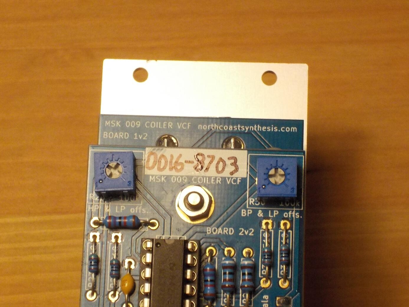
I determined the target values for Leapfrog phase shifts by building a software simulation of the circuit with everything already adjusted perfectly, and then measuring the phase shifts in the simulation. Simulation was also relevant for the Coiler VCF, but at an earlier stage in designing the procedure. There are two offset trimmers in the Coiler, which control the offsets on three outputs. It is necessary to compromise among the three output offsets, since they are not independently adjustable. I ran a "sensitivity analysis" in ngspice and found that the trimmer R20 has a strong effect on the HP and LP outputs (not the BP, to any great exent), while R30 primarily affects the BP and LP outputs (not the HP). Those facts are not at all obvious when looking at the schematic, and they fed into my decisions on which measurements to tell builders to check while adjusting each trimmer. Other things, in particular the setting for filter frequency while adjusting the offset trimmers, had to be determined by trial and error after examination of the results from trying to adjust prototypes.
In summary, the adjustment procedure for a circuit is important and often overlooked in DIY designs. In a commercial environment, it really matters because it costs real money. I'm described some of the considerations that go into designing circuits to be adjusted, and some of my own experiences with applying those principles in my commercial modules.
◀ PREV New look for DIY kits || The Truth About Ferrite Beads Will Shock You NEXT ▶