Driving LEDs digitally
2019-04-15 electronics design
In the last entry I described the electrical requirements of LEDs and how to drive them in the context of analog circuitry. When you want to indicate information with the brightness level of a single LED, as in my Transistor ADSR where the LED directly shows the progress of the envelope, it's appropriate to use an analog driver which provides current proportional to the desired light output. But another common use of LEDs is many of them at once, to display information like the shift direction in an octave switch, or even numeric digits in a 7-segment display. For those kinds of applications, it's appropriate to use a digital style of driver circuit.
Direct from a digital signal
When a digital signal has the right voltage and current drive capability, sometimes you can just connect an LED to it directly, with an appropriate current-limiting resistor. For instance, classic CMOS logic gates have basically rail-to-rail output. With those chips, logic low is 0V, logic high is the gate's power supply voltage (which might be 5V for MSI chips used in present-day hobbyist circuits; really traditional CMOS would operate at as much as 15V), and there is considerable drive capability, maybe a few tens of mA, at both voltages. So you can just calculate an appropriate resistor (design procedure given in my last entry) and use the logic signal to drive the LED. By connecting the LED to the positive supply or 0V, you can get positive logic (LED on when signal is high) or negative logic (LED on when signal is low), or even use two LEDs (each with its own current-limiting resistor) and have one driven each way.
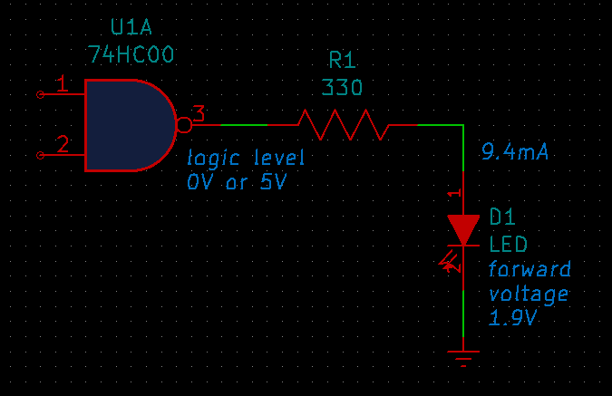
Note that any logic signal with the right voltage and current capability will work. It doesn't have to be a logic gate output, but could well be a microcontroller GPIO pin.
One thing to watch out for with direct drive is that you mustn't overload the chip. It's quite often the case that a chip will have limits like 10mA per output, which is enough for most LEDs, but also no more than 80mA for the whole chip. Connect ten LEDs to such a chip and try to drive them all at once, and it'll be a problem. This kind of information is given in the data sheet for each chip, and it's important to read that carefully.
Using a transistor switch
Not every logic signal has the right voltage and current capability to drive an LED directly. Many microcontrollers run at 3.3V now, which doesn't leave much voltage for the current-limiting resistor to do its job (especially not if you want to drive a blue LED). TTL gates are rarely seen nowadays, but when they were relevant they also had issues because they didn't swing all the way to the +5V power supply. Large, bright LEDs or displays of many of them may require more current (per output, or total) than a microcontroller can safely provide. In any of these cases, it can make sense to add a discrete transistor to sink the necessary current.
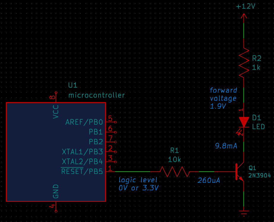
Remember that when an NPN transistor turns on, its base will float to about 0.7V above its emitter. The input to the circuit only needs to go a little bit above that to allow some current through R1. Then the transistor will attempt to draw through its collector an amount of current equal to the base current, multiplied by the transistor's gain. The usual rule of thumb is that the transistor gain will be about 100.
Normally, you'd design this circuit so that the theoretical collector current for the transistor is quite a lot more than the LED current; then the transistor "saturates," bringing its collector to a low voltage (0.3V typical for most small transistors, but the data sheet for the specific transistor may specify a value), and the actual current through the collector will be set by the current-limiting resistor R2. The power supply for the transistor can be as high a voltage as you want, within the limits of the transistor; in particular, it can be more than the input "high" voltage.
For example, suppose we want to drive a red LED (1.9V forward voltage) at 10mA from a +12V supply, with input logic levels of 0V and 3.3V. On the input side: let's call the transistor gain 40 (so that if it's less than the typical 100, it'll still work; the 2N3904 data sheet validates this as a minimum value for the gain at 100μA input, increasing for more base current). Then for 10mA output we need 250μA input current. R1 goes from 3.3V on the left to 0.7V on the right when the transistor is turned on, a voltage drop of 2.6V. To pass 250μA it would be 10.4kΩ; let's call it 10kΩ as a convenient standard value. On the output side, with the transistor saturating at 0.3V voltage drop, plus 1.9V for the LED, that leaves 9.8V across R2. To pass 10mA it would be 980Ω; that's close enough to 1kΩ.
One thing to watch out for with the basic transistor switch to ground is that the input shouldn't go significantly negative. It's normally a circuit used internally to a module, where the input to the circuit is reasonably well-controlled, is not coming from the outside world, and is limited to a range of 0V up to some positive voltage. A too-high input voltage is probably not going to be a problem because with the resistance that would typically be used, even a voltage much higher than expected logic levels would still only be able to drive a few milliamps into the transistor, and that won't damage anything. But if the voltage applied to the base of the transistor is coming from the outside world and it could go negative, then it would end up being applied as reverse bias across the transistor's base-emitter junction, and as described in my guide for the perplexed, most transistors can only handle a few volts in this mode before breaking down. If there's a possibility of this circuit needing to handle negative input, it would make sense (as described in more detail in that article) to add a protective diode from ground to the transistor base.
Sometimes a digital chip will provide a transistor switch to ground, similar to this circuit, built right into the chip. For instance, the LM339 comparators used in my VC Octave Switch module have "open collector" outputs. They're capable of sinking current to the negative power supply rail even from a source that goes above the chip's own positive power supply (within certain limits, described in the data sheet). The actual circuit used in the module is a little more complicated, as described in its manual, in order to convert pairs of LM339 open collector outputs into a tri-state current drive for each tri-state LED. Open collector output is quite common in analog comparator chips like this. Many microcontrollers also offer a configurable "open drain" mode ("drain" because they're using MOS transistors instead of bipolar) capable of withstanding more than the chip's own power supply voltage, for at least some GPIO lines; that mode can make tasks like driving LEDs somewhat easier.
Constant-current drivers
If an LED is drawing 10mA from the power supply when turned on, and 0mA when turned off, then turning it on and off means the current consumption of the entire circuit goes up and down by 10mA. If the circuit is something like a Eurorack synthesizer module, 10mA may be a significant part of the entire power consumption of the module. For instance, my transistor mixer (which doesn't have any LEDs in it) only draws 9mA from the positive rail under ordinary conditions anyway. Adding an LED that draws 10mA would more than double it; and switching that LED on and off at audio rates would have the effect of coupling a pretty strong audio signal into the power bus. More if there are more LEDs; and some of the multiplexing schemes described below do routinely involve turning many LEDs on and off at audio rates.
Everybody's worried about "bleed" in modular synthesizers, and everybody's inclined to blame their VCAs for it even if the real problem is the power system. Everybody also wants to save money on power distribution; wigglers would boil spaghetti in salt water and call it a DIY power bus if only they could figure out how to attach the ribbon connectors, and that's only a slight exaggeration. So coupling audio frequencies into the power bus may be asking for trouble. A multiplexed LED display in a module may be a real problem if not handled with care, and even single LEDs can cause issues. I used to have an envelope (not one of my own design...) in a cheaply-powered case that would put a click into my audio any time the envelope triggered, even if the output wasn't patched into anything, and I think the click came from the sudden power demand of lighting up its LED.
How can we avoid having that happen?
One thing to do is to build better power filtering. Even just making sure the bypass capacitors on the module are big enough, helps a lot. The bypass capacitors will eat the high-frequency components of the transient created when the driver turns on and off. It's possible to run the LEDs off a power filter of their own to try to keep interferance off of the main power bus. Multiplex schemes can be designed to run at frequencies as high as possible to make them easier to filter. But another approach is to reduce the variability of the LED power demand in the first place.
One can simply use lower-current LEDs, as I do in the Transistor ADSR. The indicator in that module is a high-efficiency type capable of lighting as brightly as I wanted on less than 1mA; even if it turns on and off at audio rate (which is possible in some of the intended patches), it'll have less impact on the cleanliness of the power bus than would a driver that switched 10mA for a lower-efficiency LED.
But another thing people sometimes do to avoid putting spikes into the power system is to build a driver that will consume near-constant current regardless of whether the LED is on or off. How it's done varies a lot, but here's a simple example.
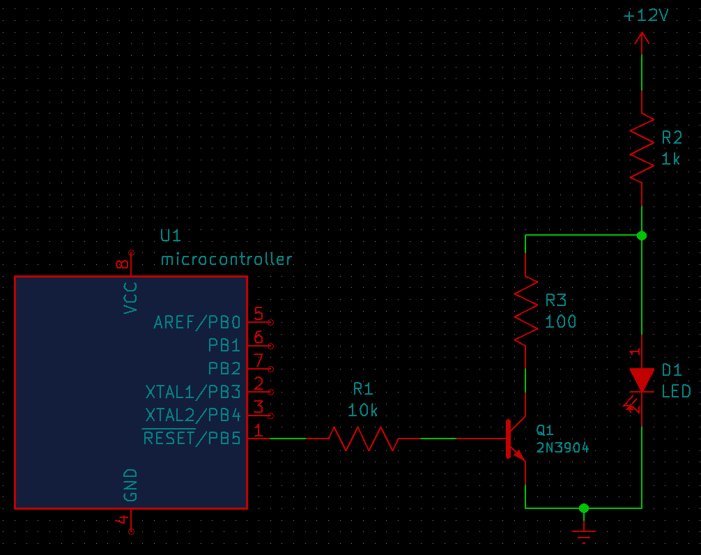
Note that this is an inverting driver; the input should be high for LED off and low for LED on. If we ignore the transistor and R3, this is just a standard resistor driver for an LED. I'm imagining it as a green LED with a forward voltage of 2.1V. When the transistor is turned off (low input), the circuit just puts 9.9mA through R2 and the LED. But if the input goes high, the transistor turns on, and diverts the current around the LED. If it saturates to 0.3V, then R2 and R3 form a voltage divider taking the voltage at the LED anode to about 1.36V, at which voltage the LED will be turned off and basically consume no current. (I deliberately chose this voltage to be a fair bit lower than the LED's forward voltage drop to be sure of correct operation if the transistor doesn't really saturate at 0.3V.) The current through the circuit with the LED off is 10.6mA. That's not exactly the same as with the LED on, and the transistor base current also makes a difference, but it's still much less difference between on and off than with a circuit that turned the main current on and off entirely. By drawing the current basically all the time and just routing it through or around the LED, we've significantly reduced the amount of noise potentially coupled into the power supply. A fancier implementation of this approach could use an op amp constant-current driver instead of the resistor R2, in which case the total current consumption could be made to vary even less.
Of course, this is arguably a waste of power: it's burning a lot of current when the LED is off just to reduce exposure of the LED on/off signal to the power bus, which in turn is only an issue at all if you believe that the power supply cannot really do its job of eating variations in load. Whether you consider the extra power to be a problem depends on your priorities.
Matrix multiplexing
A 7-segment LED display has seven individual LEDs per digit. Eight if you also count the decimal point; and fancier displays might have even more, such as the 14 segments plus decimal point, per digit, for the alphanumeric LED displays used in the Mutable Instruments Yarns. If you use a GPIO pin from your microcontroller for every individual LED in the display, you're going to run out of GPIO pins. Even apart from the limits of the microcontroller's I/O, it may be hard to fit enough pins on the package of the display itself to allow two for every segment. We need a way to save pins.
Here's one way to do it, a typical design for a four-digit seven-segment LED display.
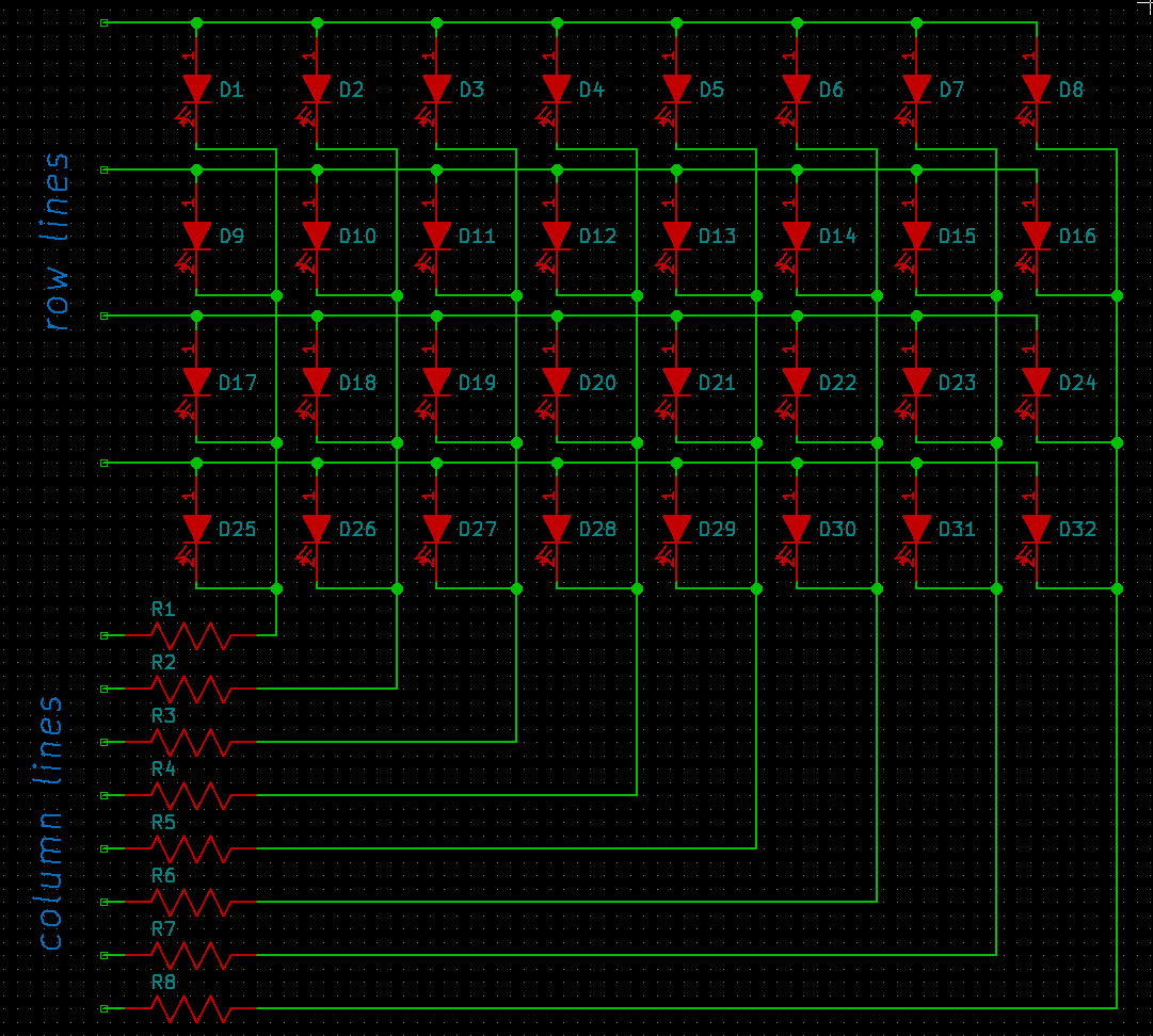
It's assumed that a microcontroller will drive this display through the four row lines and eight column lines, a total of 12 GPIO pins to drive 32 LEDs (which might well be four seven-segment digits with decimal points). That's much better than requiring 32 GPIO pins; and if the matrix is larger, the proportional saving in I/O resources may be even greater.
To light up some combination of LEDs in one row, the microcontroller brings the row line for that row high (all others low), and the column lines low for all the LEDs in the row that should be turned on (high for LEDs that should be off). The desired LEDs will be forward-biased, each with its own current-limiting resistor. All other LEDs in the display are reverse-biased or see zero voltage, and stay dark. It's necessary that the LEDs be able to withstand the reverse voltage involved, but that's not usually a problem.
In general, the microcontroller can't safely light up LEDs in more than one row at once. There may be no pattern of highs and lows on the row and column lines to produce the correct pattern of forward-biased LEDs, and the current-limiting resistors may not have the right values for driving more than one LED in parallel. But the microcontroller can cycle between the rows at some high speed. If it lights up all the desired LEDs in the first row for let's say 1ms, then lights the desired LEDs in the second row for another 1ms, and so on, it can cycle through all four rows at a rate of 250Hz, and to a human eye, the LEDs will look like they remain on steadily.
LED displays such as seven-segment digits usually come pre-wired for matrix multiplexing, with one "common" connection shared by all the segments in a digit and either a connection for every individual segment, or (in multiple-digit displays) another set of connections going the other way, for sets of corresponding segments in all digits. Multiple LEDs in a package may be "common anode" or "common cathode" depending on which end of the LED goes to the shared connection. Similar wiring is possible for some other kinds of multi-LED modules, such as "RGB LEDs" with three different colours in a single package and usually four pins (one common, one per colour).
But it's also entirely possible to wire up plain single LEDs in this kind of matrix; or even mix those with prepackaged multi-LED displays. The matrix shape and assignment of individual LEDs to matrix positions can be whatever is convenient for the microprocessor I/O resources available.
Charlieplexing
In some cases, especially when the number of microcontroller I/O pins is very limited, it's important to get the absolute maximum number of controllable LEDs, and it can be possible to go a little further by making use of the special features of microcontroller GPIO pins.
With n GPIO pins, the matrix scheme allows for controlling up to n2/4 LEDs. It calls for all the pins to be driven high or low at all times. But microcontrollers can often put their GPIO pins into a third state - "high impedance," where the pin is neither driven high nor low. Clever use of the third state can bring the number of controllable LEDs up to n2-n. For instance, with just four GPIO lines, a conventional matrix could only support four LEDs (no benefit over driving them directly), but with careful use of tri-state outputs four GPIO lines can control up to 12 LEDs.
Today this scheme is usually called "Charlieplexing" after Charlie Allen of Maxim Integrated, who proposed it on an Internet mailing list in 1995 as a development from the implications of a design by Graham Daniel. The same technique had been independently discovered several times already, and was used by other designers at least as early as the 1980s; it's probably not possible to determine who should be credited for really doing it first.
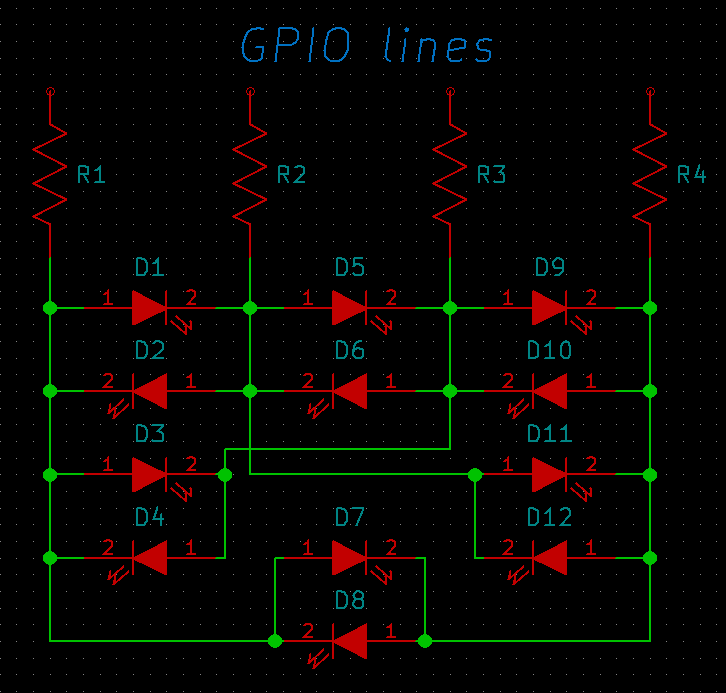
Instead of having separate row and column lines and always matching a row with a column, here the four GPIO lines are treated symmetrically. Any of the four can be driven high, any of the remaining three can be driven low, the others will be put into the high-impedance state, and then there is one LED for each of the 12 possible ways to do that. The current-limiting resistance is split in half, with one half-value resistor on each of the GPIO lines. LEDs not selected will all be reverse-biased, unbiased, or forward biased with at most half of their standard forward voltage, which is not enough to light them up.
This circuit has a number of limitations. It can only properly light up one LED at a time, so if it's generalized to even more than 12, it may start to push the limits for overall brightness. As the amount of time an LED can be turned on decreases, it must be made brighter during that time, with higher current, to compensate for the reduced duty cycle. Because of the way the current-limiting resistances work, the circuit as shown requires all the LEDs to have the same forward voltage. The required pattern of interconnections for the LEDs may not line up with what is built into things like seven-segment display modules. And large Charlieplexed displays with many segments require significantly more software complexity to drive the control lines in the right patterns than would be required for a basic matrix.
More complicated Charlieplexing circuits, with either one resistor per LED or a different way of sharing the resistors, can address differences in LED forward voltage. There are also some related designs which allow for lighting more than one LED really simultaneously, which reduces the issues with short on-time during multiplexing. The wiring and software complexity issues may or may not be important depending on the application.
Overall, because of the implementation issues Charlieplexing is seldom used for really large and complicated LED displays. But for the number of individual LEDs in a small to medium-sized synthesizer module, and when using microcontrollers with limited I/O, it can be valuable as a way to save pins. The key, as with many things in modern electronic design, is that keeps the component count down, by moving complexity into software.
Smart LEDs
Another way to keep the component count as small as possible is to build extra circuitry into each LED. It's cheaper to have one complicated component than many simple ones, and digital logic takes up very little physical space - so why not have a complete driver circuit and serial bus interface for talking to a microcontroller, built right into the LED?
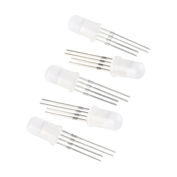
The Sparkfun COM-12986 (probably a rebranding of some other manufacturer's product - I don't think they manufacture their own) shown above is a typical "addressable" RGB LED designed for connection to a microprocessor. Instead of just being one LED, it's really three - red, green, and blue, which can be mixed to provide arbitrary visual colours - but the four legs of the package aren't just one per LED and a common. Instead, those connections go to a driver chip that is also encapsulated in the epoxy package.
To drive one of these LEDs, you just hook up two of its legs to 0V and +5V power for the driver chip. The remaining two connections are "data in" and "data out." One LED's data in goes to the microcontroller, and then any additional LEDs are daisy-chained from there using the data out. There's a simple shift-register protocol by which the master microcontroller can send commands to the chip in each LED along the chain to tell it what colour to display and the brightness. In theory there's no limit to how many LEDs can be controlled from a single GPIO pin, although the rate at which they can be updated will slow when there are more of them.
The idea of having an entire controller, serial interface, three LED dice, and current drivers for them, built into a standard 5mm LED jellybean package and having that be the cheapest way to do things, is somewhat breathtaking to those of us accustomed to the old-fashioned kind, but these are the times we live in.
So I've reviewed digital ways of driving LEDs, from simple current-limiting resistors attached directly to the signal lines, on up to smart LEDs that do all the work for you. That should shed some light on how digital synth modules manage their blinky displays.
◀ PREV LEDs and analog drivers for them || What is flux? NEXT ▶