Gracious Host development adventures
2021-07-04 USB digital development MSK 014
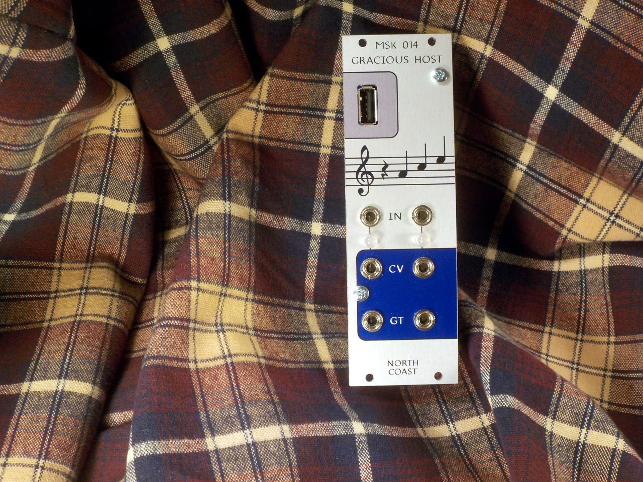
The MSK 014 Gracious Host is planned to be the next new module from North Coast Synthesis, and I've spent a lot of time in the last few months working on the firmware for it. I did most of the hardware design last year, but then shelved it for a while to do more time-sensitive work on module production and custom panels. Here are some pictures and commentary from the ongoing development effort.
For those wondering about the custom panels: I hope to have custom-panel modules available later this month. At the moment the panels are done and photographed, but I'm still working on "naked" (panel-less) assembled modules to have ready for adding the panels as those get ordered. There are also some annoying Javascript issues to sort out in the storefront. Keep an eye on my Twitch channel; I hope to do a lot of the remaining naked-module assembly on stream this week.
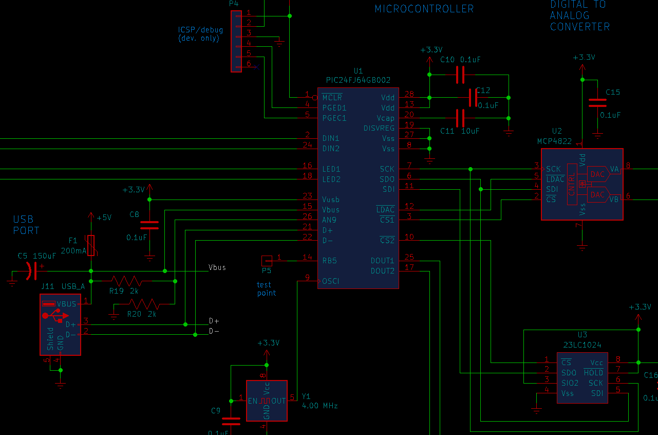
Doing digital electronics at all, let alone USB, is tricky if you want it to be through-hole. The hardware platform for this project is a Microchip PIC24 product that has USB hosting hardware built-in and is still (for the moment, at least) available in DIP format. Here's a clip from the module schematic.
After I had the basic hardware design I ordered a few PCBs so I could build a first prototype. Here's a photo of one of them. It wasn't easy to get a good view of the point I want to illustrate. This image has been heavily processed. But you can probably see what stands out about it.
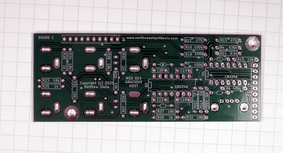
Yes, the slotted hole below the text "MSK 014 GRACIOUS HOST," near the centre of the board, is missing its slot. The metal pad just goes over solid fibreglass.
That would be a showstopper if these were production boards, but fortunately, for the one prototype I wanted to build from this small batch of boards, I was able to just clip off the leg of the jack socket that ought to have gone through that missing hole, and solder in a bit of wire to make the connection elsewhere on the board. The PCB contractors gave me a refund for the bad boards.
One of the things I want people to be able to do with the Gracious Host is change the firmware by inserting a USB key with the new firmware in a file. The chip only has 64K of flash "program memory" and 8K of RAM. The obvious way to do a firmware update would be for the old firmware to talk to the USB key, load the new firmware from there into unused space in flash memory, then once all the new firmware is loaded, transfer control to that, inactivating itself. Trouble is, that process requires two copies of the firmware to be able to fit in program memory simultaneously. The firmware can't comfortably be more than 32K. And the C-language drivers provided by the microcontroller manufactuer, with the necessary higher layers for communicating with a USB key and decoding a FAT filesystem, come to something like 50K, even before whatever other space would be consumed by my own code. Those drivers are really meant for use on larger chips in the PIC24 family, not this one in particular; but the larger chips aren't available in through-hole.
My solution was to add a 128K serial RAM chip (lower right in the schematic clip). I figure having that space will be useful for other things the firmware might want to do anyway, and it allows for a much larger firmware image. The old firmware can load the new firmware from the USB key to the SRAM, then a minimal "update" routine, which will be only a couple of kilobytes, can burn from there into program memory, overwriting all the old firmware except itself before the new firmware takes over. This way the firmware can come much closer to filling all of the program memory, while still allowing for update from USB.
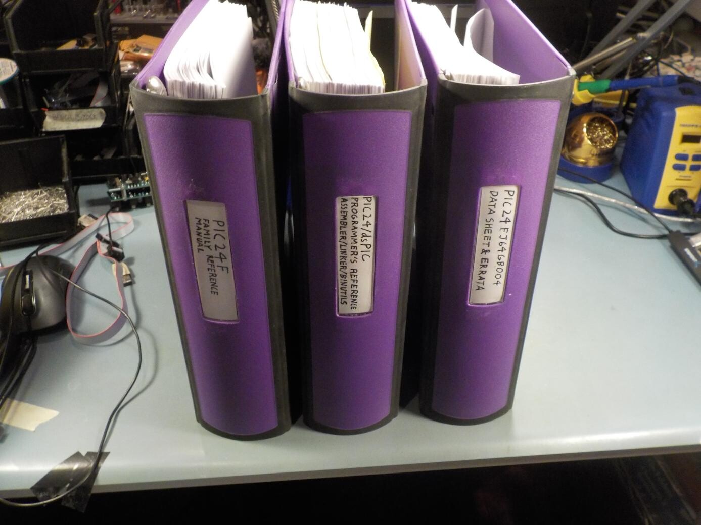
The manuals for programming the PIC24 chip fill three large binders. Nonetheless, there's a lot of important information not in these manuals, which I've had to learn by experiment.
Spending 50K out of 64K just on the vendor's USB driver (and a corresponding large majority of the very limited RAM space) is still a problem, though. I want to be able to fill that chip with my own code, or have the space available for third-party firmware. There are also some serious issues with licensing on the vendor's code and C tool chain. The tools are largely derived from the GNU Compiler Collection, and therefore necessarily subject to GPL, but Microchip attempts to lock important features they inherited from GCC behind a "license server," and they demand subscription fees in a way that is probably illegal. Instead of using the vendor's USB driver, I had to write my own - much smaller than the vendor's, and in assembly language. Microchip hasn't copywronged the (also GNU) assembler very much, probably because they think nobody is crazy enough to try to do serious development for these chips entirely in assembly language.
Getting my own all-assembly-language USB driver working has indeed been a challenge, but at this point I have it working well enough that I can start making serious progress on the application-level code that goes on top.
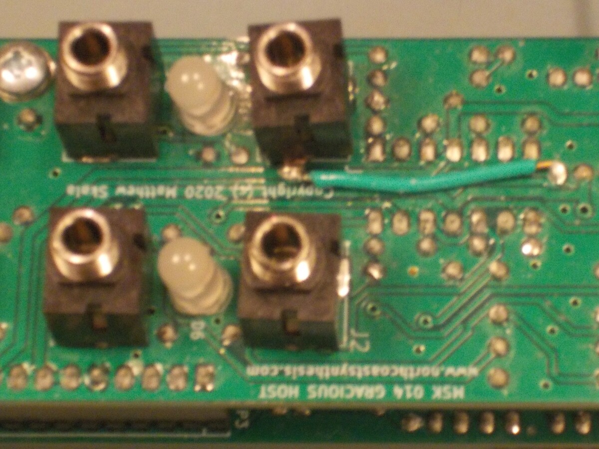
Here's a view of the back of the prototype, as it currently exists with some modifications I've made in the last few months to aid debugging. In production versions I plan to have it draw power for the microcontroller, and the attached USB device, from the Eurorack +5V bus - which will be required. Given how much current some USB devices need, it really doesn't make sense to try to get all the power from the analog +12V bus (and risk contaminating that with noise). But for this prototype, which I run from my bench supply most of the time, I've added a 7805 regulator so I can power it with just ±12V.
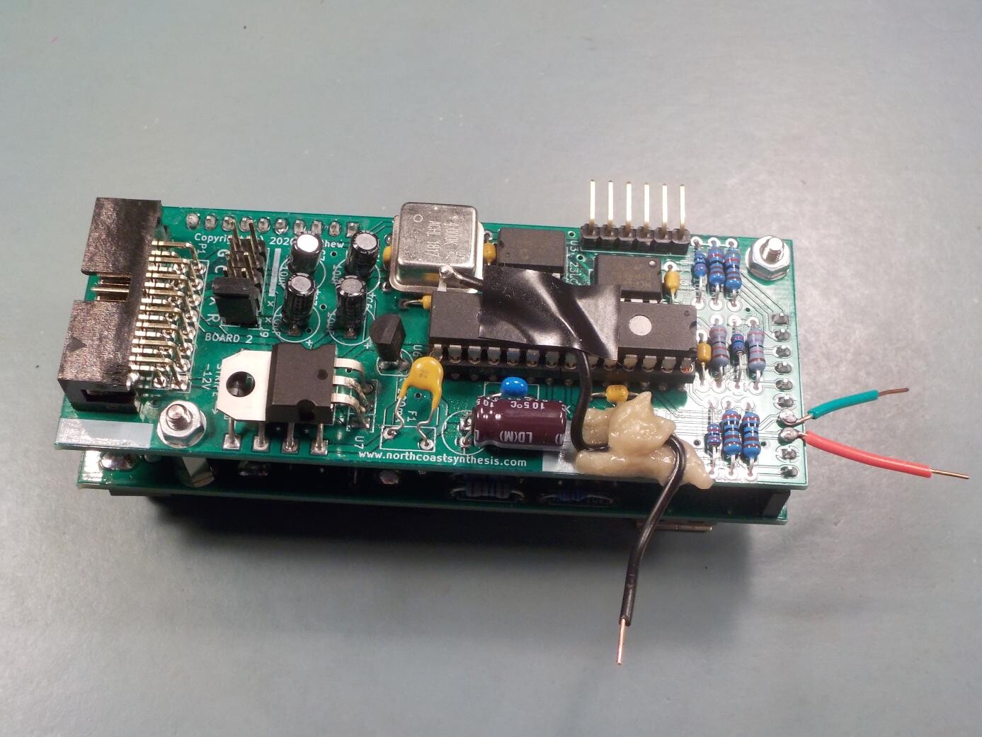
The right-angle header sticking out at the top is for Microchip's "PICkit" debugging tool, which lets me single-step through the firmware and reflash it in-circuit. Red and green wires at right give access to the data lines of the USB bus. And the black wire at the bottom (with glue and tape, leading to a bent-up pin on the microcontroller) goes to a GPIO pin so that I can send debugging signals out of the firmware. That pin was originally planned to be unused, and was grounded on this version of the PCB, which is why I had to bend the DIP pin up and make the connection with a wire in the air.
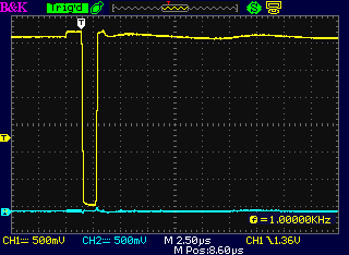
A lot of issues in USB driver programming are closely connected with timing, and single-stepping through the code doesn't necessarily work well for debugging such features. It's important to know what's actually being sent on the bus as the firmware executes at its normal speed, and I found my oscilloscope, connected to those soldered-in wires, to be a useful debugging tool. Shown here is a "low-speed keep-alive pulse." When a low-speed device (like a mouse, or a typing (qwerty) keyboard) is attached, the host is supposed to send one of these every millisecond if there is no other traffic on the bus. The device listens for them, and shuts itself off if three in a row are missing. I had a heck of a time making sure these pulses would always be sent when needed.
USB 2.0 has different speeds: "low speed" of 1.5Mbps for things like mice and typing keyboards, "full speed" of 12Mbps for things that are a little smarter (like the MIDI keyboard I want to hook up), "high speed" of 480Mbps for stuff like cameras, and then the next level in USB 3.0 is "super speed," going up to 5Gbps by using extra wires in the cable. My hardware can only go up to "full speed," but the authors of the USB 2.0 standard were mostly interested in "high speed" because it was the new cool thing at the time. So they describe full speed mostly in terms of how to do the extra negotiation to upgrade from it to high speed, and they barely mention low speed at all. Keep-alives, in particular, are never really explained, and Microchip similarly doesn't explain the hardware support for them.
When, by trial and error guided by the scope, I finally got low-speed keep-alives working in a way that would keep my mouse satisfied, for a while I had the host also sending them into an empty bus after I pulled out the mouse. That's not supposed to happen. Here's what it looks like.
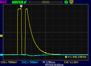
The keep-alive isn't really just a single pulse. It starts with the output driver turned off, so the bus floats at the voltage set by the weak pull-ups and pull-downs in the host and the device (if any). That appears as low voltage on this scope trace. Then the host turns on its driver and drives this data line high, low, high. Then it disconnects. So in this weird condition of keep-alives being driven incorrectly into an empty bus, you can see two high pulses and then the voltage decays relatively slowly back to zero as the cable and oscilloscope probe capacitances discharge through the weak pull-down resistance.
Once I got the keep-alives working I was able to talk to the mouse well enough to record a demo video clip. Here I'm playing a modular synth using the mouse. The X and Y coordinates of the mouse position generate control voltages for oscillator frequency and filter cutoff. The left and right buttons generate gates. The wheel in the middle switches between quantization modes. There's a lot going on in the firmware to communicate with the mouse, get those coordinates and button presses, do quantization as necessary, and then ship the signal out to the DAC chip.
That demo is cheating a bit. The host doesn't really work as well as it may seem to in the video. In particular, it's disconnecting and resetting about every twelve seconds. I had to time my moves carefully to work around that. But being able to really use a USB device to control a synthesizer, even with as much going wrong behind the scenes as I knew was the case, made me feel a lot better about the project.
I thought better test equipment might be helpful and I shopped around a bit for USB-specific debugging tools. There are devices called "protocol analyzers" specifically intended for this kind of work. Their basic function is to make a recording of what happens on the bus, which you can then read through to figure out what's going wrong with your hosts and devices. Unfortunately, the good ones were all way out of my budget. I don't expect to be doing much USB debugging except for this one module project, so I have to weigh the cost of a tool that I will only use for this one module, against how many of this module I think I can sell and the total budget for developing the module. If I could buy a tool for $5000 that would magically solve all my USB debugging problems, it wouldn't be worth it because I'm unlikely to sell enough Gracious Hosts to make up for increasing the development budget that much. Not unless I cared to develop several more USB modules and spread the cost over them all.
Someone on Twitter asked me - why do you need hardware for this? Why not just some kind of sniffer software on your PC to record the bus traffic?
It's a good question. If I were debugging a USB device - that is, a box intended to connect to a computer's USB port - then that would indeed be a useful option. Such software does exist and is reasonably easy to find. But in my case, the thing I'm debugging is the USB host itself, filling the role that the PC would normally fill. In the configuration under test, there is no PC involved at all. In order to get a PC connected to the bus in a way that will allow it to observe and record what's happening without removing the host that's being tested, it's necessary to involve some kind of dedicated hardware.
Eventually I managed to find a Total Phase Beagle USB 12, used, on eBay. I call it the "My First Easy Bake USB Protocol Analyzer" because it's pretty much the cheapest and least capable such device on the market - kind of a toy protocol analyzer for children or childish adults - and even so it would still be out of my budget if I were buying it new. But the seller only wanted about half of the new price. He said he'd found it literally in a thrift shop in Austin, Texas, and wasn't sure what it was, or whether it worked. I decided to take the chance.
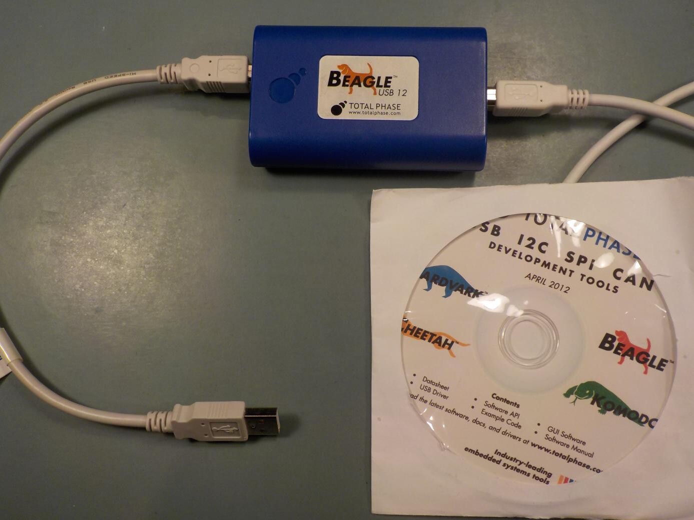
The analyzer connects through the cable at the right, to a laptop that controls it and saves the data. The cable at the left goes to the host that's being tested - which can be another port on the controlling laptop (useful for getting a "believed good" reference recording) but would normally be my host module. USB devices plug into a port on the analyzer next to where the short cable plugs in.
Note the date on that software CD. When I got the old software loaded onto my recent Linux machine, I found that none of it would run with current kernel and library versions. Fortunately, Total Phase is still in business, and they still support the Beagle USB 12 - mostly, I suspect, as an advertisement for their higher-end products. I was quickly able to find a more recent version of the software that would be compatible with my system. There are an awful lot of greyed-out disabled options in the menus, and messages saying "Sorry, the My First Easy Bake USB Protocol Analyzer can't do that, would you like to view our catalogue of more advanced products?" But it does do the basic job of recording and decoding bus traffic.
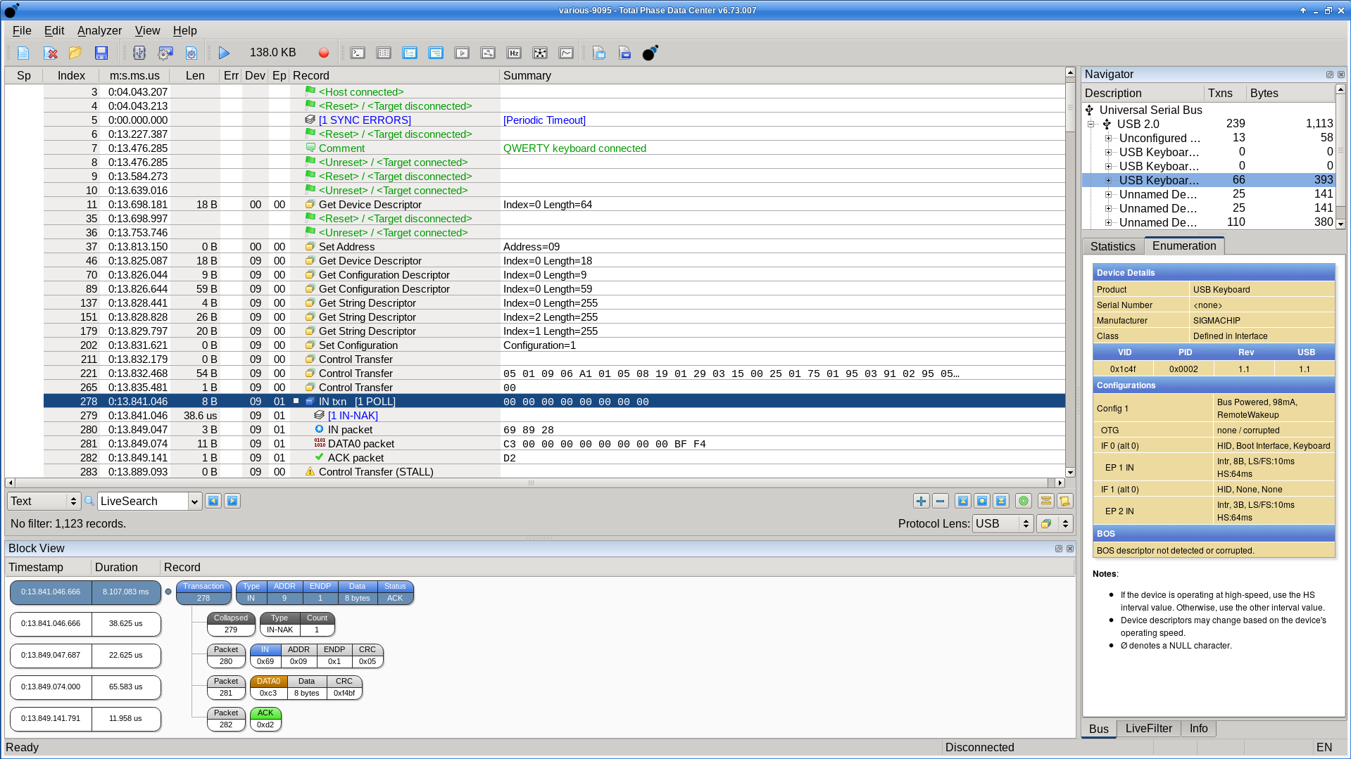
These kinds of recordings have been some help in debugging the USB driver, and I hope to get a lot of use out of the analyzer a little later, when I'm working on the communication with USB flash drives to load files. I've been disappointed, though, at how little help it has been for most of the problems I've faced so far. The analyzer operates at a relatively high abstract level; when the host or device sends a valid USB packet onto the bus, the analyzer records that fact and captures the data from the packet. But the hardest problems I've faced have been at a lower level - stuff like "oh, this packet was sent three microseconds too early, so it collided with another packet." In that case the analyzer just records the fact that there was a garbled invalid signal on the bus, not the sub-packet timing details I would need to really figure out what went wrong. There are other analyzers capable of doing that lower-level stuff, but they cost a lot more.
Instead, I ended up going back to the oscilloscope for a lot of my debugging work. I got a lot of mileage out of the hardware equivalent of "printf debugging": just adding instructions at different points in the firmware to send pulses of different lengths to a GPIO pin, then using the scope to watch that pin and one of the bus lines.
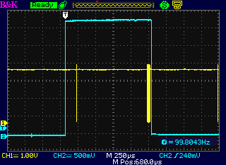
Shown above: the cyan trace goes high when the user-level software asks the USB driver to make a transaction. That happened just a little too late to fit in the current 1-millisecond USB low speed frame, so we see just a keep-alive (narrow yellow pulse) at the frame boundary. A millisecond later, the transaction goes through (wider yellow burst) and shortly after that, the cyan trace goes low indicating that the driver has returned successfully.
That's how it's supposed to work. I had a lot of bugs to fix, though, especially when communicating with a dollar store typing keyboard that I was using for testing purposes. For a while, it was failing if I made two requests to the driver in consecutive milliseconds. Then I got that working, but it started failing if I didn't make a request in every single millisecond frame. Here's a scope shot I made while working on that one. The cyan pulses represent interrupts processed by the microcontroller, different widths for different interrupt sources.
There is a "start of frame" interrupt that warns the microcontroller when the start of the next frame is about to come up; that is supposed to be a good time to set up the next request, so that it can execute immediately at the next frame. That happens at intervals of 1ms. But there is also a "1ms interrupt" that is also supposed to happen at intervals of 1ms. The two millisecond ticks evidently do not derive from the same clock source because they drift relative to each other - the "start of frame" interrupts being more accurately one millisecond apart. I had things breaking randomly just at the moment when these two interrupts drifted in the phase where they would almost coincide. I think that may have been part of the cause of the periodic resets in the video earlier.
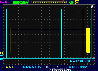
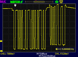
Here's a zoomed-in shot of one of the data bursts. The host asks the typing keyboard "Have any new keys been pressed?" (INTR IN packet) and the keyboard replies "No new keys" (NAK packet). You can see where the bus turns around (host disconnects, keyboard connects) by the change in DC levels; the keyboard driver's "high" and "low" levels are a fraction of a volt higher than those of the host. Also note that the scope is reporting the frequency as "19.0000kHz." The low-speed IN/NAK transaction is the same every time and it contains 19 rising edges, on which the scope is configured to trigger. One thousand one-millisecond frames per second makes a 19.0000kHz triggering rate. At the time this shot was captured, I was still doing an INTR IN every single millisecond because the driver would break if I didn't.
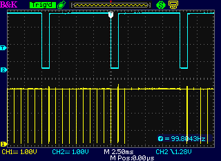
Later, I managed to resolve the problem that was causing it to break if I didn't do a request every millisecond. It was because successful requests were not fully cleaning up a data structure, so that if the one-millisecond interrupt happened after a successful request without a new one being placed, it would read the bad data structure and crash. Filing a new request within less than a millisecond recreated the data structure and prevented the crash. Once I fixed that, I was able to make it do requests to the keyboard at the slower rate of one per 10ms (as this keyboard specifies in its configuration descriptors). Note the much longer time scale on this scope shot. The cyan trace represents time spent in a delay function in the firmware; after each delay it makes one request and an IN/NAK burst like the one shown above goes across the bus. In other milliseconds, only a short keep-alive pulse goes by, and the scope's sampling misses some of those in the lower right quadrant of the image.
◀ PREV Marbled and hydrographic panel gallery || Fat sounds and thick pads NEXT ▶