Exponential converters and how they work
2018-10-12 electronics design
Exponential converters are basic building blocks used in many synth circuits, but for many of us, they are incomprehensible black boxes. The basic concept of how an exponential converter works is very simple; but the simplest possible circuit for the purpose has many serious limitations, so it's usual to add several layers of additional circuitry to compensate for different effects and make the overall behaviour more predictable. As a result, the exponential circuits we actually see in common use may look dauntingly complicated to beginning designers, and it may not always be easy to recognize the simple underlying principle. In this article I'm going to build up to a real-life level of complexity starting from the simplest possible exponential converter circuit.
Why an exponential converter?
As I discussed in my piece on VCAs, most human senses are logarithmic. We perceive differences in physical phenomena - in particular, the frequencies of sounds - according to the proportion of the underlying physical quantity, not according to the absolute quantity. For example, the difference between 220Hz and 440Hz sounds the same as the difference between 440Hz and 880Hz, or even between 55Hz and 110Hz. Each is one octave. This fact allows us to get useful information from our senses at many different scales, at both ends of the spectrum. If instead we perceived pitch in a linear way, we could either have good perception of pitch at the highest audible frequencies and no useful resolution at the lowest, or else we could usefully resolve very low pitches but be completely overwhelmed by the information in high ones.
Both to provide a better analogy to human perception, and because the circuits themselves face the same issue of needing to respond well over a wide range of scales, it is usual in modular synth electronics to use logarithmically-scaled voltages for controlling frequencies of oscillators, filters, and so on. The modules correspondingly have exponential voltage-to-frequency response. In Eurorack, we usually use the standard of 1V/octave: each increase of 1V in the control voltage doubles the frequency. There usually is not any fixed definition of what ranges of voltages are valid, or which frequency corresponds to zero voltage. Those things depend on the tuning settings of the modules involved and may change during a performance. But if you happen to have your oscillator set so that 0V corresponds to 110Hz, then when you give it a 1V control voltage it will tune to 220Hz, at 2V 440Hz, and so on.
Logarithmic control voltages are not the only way to do it. Some synths, particularly older ones, instead use linear voltage control (often called Hz/volt), where the frequency is supposed to be directly proportional to the input voltage. That can simplify some of the circuits, in particular by significantly reducing the need for exponential converters. But it also suffers from exactly the problems the logarithmic system is meant to solve.
The question of logarithmic versus linear voltage control is not only relevant to frequencies. Voltage-controlled amplifiers face the same question of whether to respond linearly (output gain directly proportional to input control voltage) or exponentially (responding to a logarithmic control voltage). In Eurorack, both kinds of response are popular for VCAs, and some VCA modules can even switch or interpolate between them.
Circuits that require an exponential response to voltage usually contain some kind of "core" that really is controlled by a linear current. In order to make them respond properly to the logarithmic voltage input, it's necessary to generate a current that is an exponential function of the control voltage. That is what the exponential converter does. Most synth circuits that have an exponential response to some voltage, will contain an exponential converter. Here's one from the Thomas Henry 555 VCO:
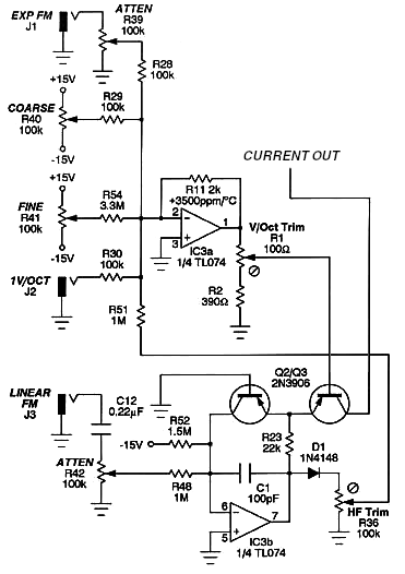
As you can see, it's a fairly complicated circuit, with many features built into it. Where to begin on understanding something like that?
Transistors and their exponential response
One of the basic rules for understanding transistor circuits is that the base is always one diode drop, a fixed voltage of approximately 0.7V, above the emitter. That is discussed in the "Circuit explanation" chapter of the North Coast Transistor Mixer manual, and as I caution readers there, it's a useful approximation good enough for understanding many circuits, but it's not the whole story nor the final word on how transistors work. To understand exponential converters, we need to go a little deeper.
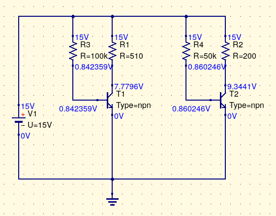
That "diode drop" (as is also the case with actual diodes, not only the base-emitter junctions of transistors) is not really a fixed voltage. Actually, it is very close to a logarithmic function of the current through the transistor (base current or emitter current it doesn't matter, because those are directly proportional to each other at this level of analysis). Every time you double the current through the transistor, you increase the base-emitter drop by about 18mV. In this simulation output, note that the transistor on the right is passing twice as much current (as you can infer from the base resistors R3 and R4), and the base voltage on the right is 18mV greater.
And it also works the other way around: if you can force the base-emitter drop to be a fixed voltage by some means, then the current through the transistor will be an exponential function of the base-emitter voltage, doubling the current for every 18mV of voltage increase. As a mathematical expression, it looks something like I = exp(aV+b).
The variables V and I represent input voltage and output current. The quantities a and b are basically constants: a represents the scale of the voltage-to-current response (how much voltage it takes to double the current; the appropriately-scaled inverse of that 18mV quantity I mentioned) and b is a constant offset describing how much current the transistor passes at some fixed input voltage.
Of course, there are limits. If you increase the base-emitter voltage by 180mV, then the current increases by a factor of 210, which is approximately 1000. Increase base voltage by 360mV, which is still not very much, and the current increases by a factor of more than one million. Too much voltage without external limiting of the current, and the transistor explodes. And at lower-than-usual base voltages, there can be tiny leakage currents that do not go away with further-decreasing base voltage, so that the compliance of the output current to the theoretical exponential curve stops being accurate.
But it's an interesting fact about bipolar junction transistors that within wide limits, they obey the exponential law with impressive accuracy. Common, low-cost general purpose transistors often match the theoretically ideal exponential curve to within a small fraction of a percent over more than a factor of 1000 range in current levels. So the design of an exponential converter nearly always comes down to scaling the input control voltage into an appropriate range, applying it to the base of a transistor, and then using the transistor's collector current as the output. That's all there is to it.
One transistor, no compensation
Here is about the simplest V/oct exponential converter I can design. Please note that it does not work well and I do not recommend actually using it; this circuit is just meant to illustrate the simple principle at the core of more complicated exponential converters.
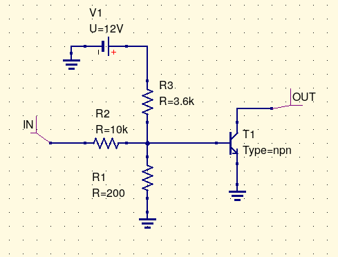
Control voltage is applied at "IN." The three resistors form a voltage divider which scales the input voltage so that a change of about 1V at the input will produce a change of about 18mV at the transistor base. The 3.6k resistor R3 to positive power offsets the base voltage so that it will be roughly 0.7V when the input voltage is 0V. Then the transistor just does its thing, passing an amount of current that is an exponential function of the base voltage, roughly doubling for every 1V of input. Here is the simulation result, where "X" is the input voltage and "Pr1.I" is the output current.
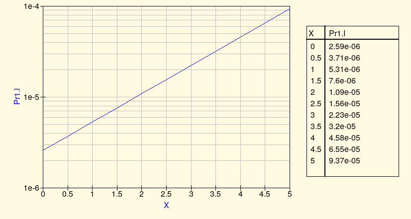
By comparing the current at whole-volt input values, it's clear that it comes close to doubling with each additional volt of input. We could make it better by perhaps making one of the resistors variable and trimming it to fit the slope as exactly as possible to 1V/oct. And note that this is already tracking pretty well over five octaves and it's not even a complicated circuit. Most of the magic is just in the natural behaviour of transistors.
So why not just use this circuit? Why do we need a more complicated exponential converter? Some synth circuits that do not need much accuracy in exponential conversion actually do use something like this circuit, but most will at least buffer the input voltage through an op amp. The plain resistor divider driving a transistor as shown here necessarily has a low input impedance and so without a buffer its tracking will be sensitive to the way the control voltage source drives it. However, the more important reason for added complexity comes down to the "constants" a and b in that transistor-current equation I = exp(aV+b).
The values a and b are not really constants. Actually, they are both highly temperature-dependent. If we build and adjust this kind of simple uncompensated exponential converter to track accurately at one moment, as soon as the temperature of the transistor changes, even by a fraction of a degree, its response to base voltage will change. Output current will pretty much always obey some precise exponential function of base voltage, but which exponential function depends on the temperature. An oscillator built on the breadboard with this kind of converter in it will literally go out of tune by a semitone or more when you breathe on it. And even if kept in a carefully temperature-controlled environment, the current passing through the transistor (especially at higher current levels) can itself heat up the transistor by a small but important amount, causing temperature fluctuations which screw up tracking. So for a response that will be accurate and stay accurate, we need to somehow deal with the effects of changing temperature.
Zeroth-order temperature compensation
In practical cases, the biggest temperature problem comes from the quantity b in the transistor-current equation, representing the overall scale of the current through the transistor. Changes in b have the effect of shifting all the output currents (thus the frequencies, when the exponential converter is controlling the frequency of something) up or down by a multiplicative factor. With the circuit that goes out of tune when you breathe on it, in practice most of that change in pitch comes from the change in b.
So the standard technique used in all but the simplest transistor exponential converters is to attempt to indirectly measure the current value of b, and adjust the voltage given to the output transistor to compensate for any changes. Remember that the transistor's exponential-current characteristic works in both directions. We can drive the base to a voltage and see exponential current at the output, but we can also force the transistor to accept a fixed current and measure the voltage at the base; and the same temperature-dependent exponential curve applies either way.
In this simulation, a constant-current source draws 1mA through a transistor with its base fixed at ground potential. The transistor will allow its emitter to drop to whatever (negative) voltage it needs for 1mA to be the amount of current it passes. We are usually interested in collector current, not emitter current, but because of the transistor's significant current gain, the emitter current will be basically the same as the collector current (negligible current is lost through the base) and anyway as long as the gain remains more or less constant, the emitter and collector currents will be proportional, which is good enough.
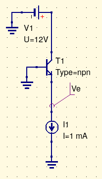
If the transistor's parameters change - which ordinarily would only be caused by a change in temperature - then the emitter voltage will change to keep up. Here's a simulation result showing how the emitter voltage in this circuit ("Ve.V" on the plot) responds to temperature (degrees C, labelled "X" on the plot).
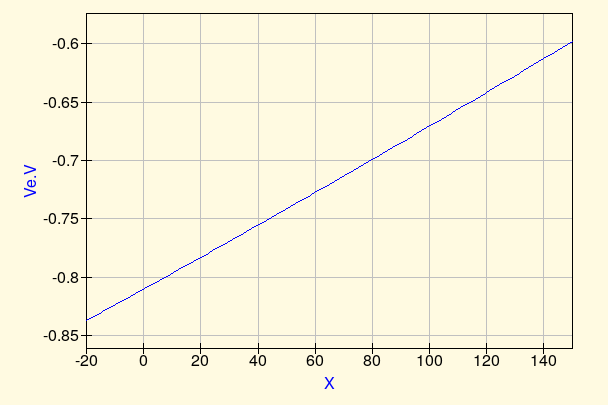
As seen in the plot, the base-emitter voltage needed for a fixed 1mA current changes quite a lot over the range of -20C to +150C. Real synth circuits are not really expected to operate over such a wide temperature range (and would be damaged by other effects at the high end of that range anyway), but even over a more practical range like 10C to 50C, the change is significant.
But this circuit provides a plan of attack for compensating changes in transistor parameters. Instead of just having one transistor to do the exponential conversion and risking changes in its parameters, we will use two. They will be two transistors of the same type, matched as closely as we reasonably can. We will try to keep them at the same temperature and operated in the same way. The idea is that the two transistors should respond to voltage and current as similarly to each other as possible. Then we will put a fixed current through one, measure the voltage needed to do that, and use that voltage to offset the scaled control voltage we apply to the second. Changes in transistor parameters, specifically the quantity b, will then cancel out.
Here's a narrower clip of the Thomas Henry circuit, showing just the two-transistor temperature compensation part.
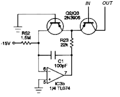
Note that these are PNP transistors; they want their emitters to be at a small positive voltage relative to their bases, opposite to how the NPN transistors in my other examples work. The main reason for using those here is that the designer wanted this to be a current source, feeding current into the rest of the oscillator which has an input at negative voltage.
The transistor on the left is called the "reference" transistor. Its base is tied to ground potential (0V). The op amp's main purpose is to keep the current through the reference transistor constant. It's called a "servo" op amp in this application. Remembering that op amps attempt to force their inputs to be equal, if we assume that the op amp is working normally, then because its positive input is at 0V, so must be its negative input, which is the reference transistor's collector. Therefore (bearing in mind that the current through the op amp's inputs and the DC current through C1 must be zero), the voltage drop across R52 is 15V, the current through it is 10µA by Ohm's Law, and that is also the (collector) current through the reference transistor. The op amp will drive its own output as necessary to force the emitters of the two transistors to whatever base-emitter voltage above 0V is needed to keep 10µA flowing through a transistor of this type. When the transistor parameters change due to temperature, the voltage will automatically adjust.
Note R23. Part of its purpose is to limit the current through the TL074 op amp output and therefore through the transistors. That op amp may be capable of driving its output as high as 12V, with current into the tens of milliamps or more. This could be enough to damage the transistors, and R23 prevents the current from going too far out of control. Calculating that the output voltage and current from the TL074 are expected to be less at the normal operating point does not suffice to protect the transistors from transients during startup, phase reversal conditions, and so on; R23 guarantees safe current under every voltage the TL074 is capable of producing. However, an even more important reason to use R23 is to reduce the voltage gain of the reference transistor. The reference transistor is effectively a common-base amplifier. Small changes in its emitter voltage translate into large changes in current (through the exponential voltage-to-current function), which create large changes in voltage when multiplied by the 1.5M current-setting resistor; thus, there can be significant voltage gain between the transistor emitter and the op amp negative input, and that is bad for stability. Adding the resistor R23 gears down voltage changes at the op amp output to much smaller changes at the transistor emitter, reducing the gain around the loop. The capacitor C1 is also meant to improve stability by bypassing short-term overshoots, as discussed in my article on op amp stability capacitors. Together, the resistor and capacitor kill the op amp's gain at high frequencies, preventing it from going into undesired oscillation. Transistors inside op amp feedback loops are often a source of stability problems and even op amps that are perfectly stable with passive resistor networks usually need some relatively aggressive compensation when there are transistors inside the loop.
Looking at the circuit again, suppose the connection labelled IN is driven to 0V by the rest of the circuit. Then the two transistors will be at identical operating points (except for the possibly different collector-emitter voltages depending on what the output is connected to; we will assume that makes no difference and in practice it makes very little). They have the same base-emitter voltages, and we assume they are obeying the same exponential voltage-to-current law. The transistor on the left is passing a fixed 10µA, and so the one on the right must be as well, passing 10µA of output current to the rest of the circuit (which happens to be the oscillator core). If the temperature changes, then the voltage-to-current law changes, and so the op amp must drive the base-emitter voltages of both transistors to a new value. But if the transistors remain matched and at the same temperature as each other, they will continue both passing 10µA. The effect of the temperature change is cancelled out!
Suppose the input circuit not shown drives the IN connection to a voltage of +18mV. The base-emitter voltage of the reference transistor is at an unknown value in the range of about 0.7V, whatever voltage would drive a transistor of this type to produce 10µA. The base-emitter voltage of the output transistor is now that value minus 18mV, because the external circuit is driving the base closer to the positive emitter voltage. Therefore the base-emitter voltage of the output transistor is such as to drive a transistor of this type, under these conditions, to produce half as much as 10µA of collector current: that is, 5µA. Similarly, if the IN connection is driven to -18mV, the base-emitter voltage for the output transistor will be 18mV greater than that of the reference transistor, and the output current will be 20µA.
What is actually connected to the IN connection is an op amp inverting amplifier with a small negative gain (-0.018). Every time the V/oct input to the module goes up by 1V, the output of that amplifier drives the transistor base down by 18mV, doubling the output current. And variations in the quantity b in the transistor voltage-to-current law, are cancelled out. The resulting V/oct exponential converter is much less sensitive to temperature changes than the single-transistor version.
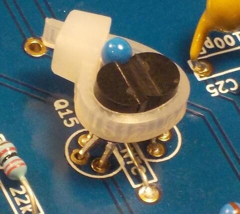
There are some wrinkles to deal with. One is that it's important to keep the two transistors at the same temperature. Ideally, they should be two transistors built side by side on the same IC. The silicon crystals out of which ICs are usually made have extremely high thermal conductivity (they are chemically similar to diamond, another material of very high thermal conductivity) and so transistors on the same chip stay well-matched in temperature. By the way, this is one reason why "discrete op amps" are pretty much baloney. Op amps use current mirrors, which need matched transistors at matched temperatures, and it's just not possible to keep the transistors really accurately at the same temperature when they are discrete transistors in separate packages. "Discrete op amps," despite being sold for high prices to the unwary, can pretty much never achieve the performance of the best IC op amps. My own commercial discrete-transistor designs, such as the Transistor ADSR, use the transistors in different ways that do not depend on matching like an op amp design would. Nonetheless, it can be hard to find integrated matched pairs of transistors suitable for use in synthesizer exponential converters, especially when balancing other goals, and so we are sometimes forced to make do with pairs of discrete transistors in this application. I like to bind them together with a cable tie, as in this detail photo from a Leapfrog VCF build. In some of my most recent Leapfrog builds I've also been adding a blob of glue on top just to help keep the cable tie from slipping off sideways, since there are limits to how tight I can pull it without risking damage to the components.
Another issue has to do with exactly how the control voltage is applied to the transistor pair. I deliberately chose the Thomas Henry 555 VCO design for my example because it uses an inverting amplifier in the input (which is a popular design, and makes a lot of sense as a relatively foolproof way to apply an op amp) and it also applies the control voltage to the output transistor, which I think is easier to understand in a basic-level explanation. But if we have a choice it may actually be better to have the output transistor's base tied directly to ground and apply the (properly scaled, and possibly inverted) control voltage to the base of the reference transistor. Doing it that way inverts the sense of the control voltage - it means the control voltage must move in the opposite direction to produce the same change in the final output current. Depending on the kind of circuit at the input, the kind of circuit consuming the output, and whether the transistors are NPN or PNP type, this may be an advantage. It may also mean needing one inversion more or less in the input circuitry to make the overall-circuit input go in the right direction.
As René Schmitz describes in his widely-cited article on exponential converters, applying the control voltage to the reference transistor means the input impedance is higher and more predictable; the input circuit must provide a constant fraction of the current through whatever transistor it is driving, which is basically a constant and probably small for the reference transistor, but could be much more for the output transistor when the output current is high, and varies with the output current. I'm not sure that's really a big deal in the most typical application, though, where the circuit driving the transistor is an op amp amplifier with plenty of current-driving capacity to spare.
The scale of the reference current ought to be comparable to that of the output current, to the extent possible. Although temperature is the main thing that causes the transistor parameters to change, the parameters do also depend a little bit on the overall current level, so if one transistor is running at a much different current from the other, the transistors will not be matched so closely. Current, especially at the higher levels, also affects temperature because of self-heating, so if the current in the two transistors can be kept roughly the same, it's easier to keep them at the same temperature. For these reasons I usually design my reference current to be about what I expect the output current to be at the (logarithmic) middle of the frequency range, or maybe a little higher than that. The LM13700 chips used both in this VCO and many of my own designs accept an absolute maximum control current of 2mA, and I usually aim for something like 100µA of reference current. I'm actually surprised to see the reference current chosen so low as 10µA in the 555 VCO. I'm not sure what the reasons for that decision were.
Finally, and most importantly: this two-transistor design compensates for changes in the value b (offset of the voltage-current function) with temperature when the control voltage applied to the transistor pair is zero, but it doesn't compensate at all for changes in a (scale of the voltage-to-current function, affecting pitches at other control voltages). With this level of compensation, breathing on the circuit probably won't drive it far out of tune, but the apparent size of octaves and other intervals - the ratio of volts to octaves which people call "tracking" - can still change with temperature; and listeners are sensitive to that. For really serious music use, we need at least one more layer of temperature compensation.
First-order temperature compensation
Remember that the V/oct control voltage goes through an amplifier with gain of (in this case) -0.018 to translate 1V/oct standard control voltages to the 18mV/oct required by the transistors. When temperature changes mean that the quantity a changes, the practical consequence is that that "18mV" amount changes. When the transistors are cold, they might only require 17mV/oct. When warm, they might require 19mV. The voltage change needed to produce a doubling of the output current is proportional to the absolute temperature (that is, the temperature above absolute zero). Synth circuits usually run at about 300K (300 Kelvin, approximately 27C), a little bit above typical indoor room temperature. A 1C change in temperature at that level means a change of 0.33%, or 3300ppm as it's usually measured (parts per million) in the voltage needed to produce a doubling of current.
We are already offsetting the control voltage to account for temperature changes, by means of the servo op amp. It would be possible to imagine having two reference transistors with say 100µA and 200µA currents, measuring the difference in voltage between them, and scaling the control voltage according to that voltage difference. Indeed, such circuits have been built. But the more common way of doing it is a little simpler: build an input amplifier whose gain also changes with temperature to match the changing temperature requirements of the transistor pair. Here is the CV input amplifier from the 555 VCO.
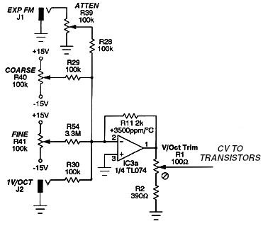
The left side of the circuit may look complicated but that's only because it has several inputs: the basic V/oct pitch control voltage; an "exponential FM" input which is just another jack with a potentiometer for attenuation; and two manual control knobs for coarse and fine initial pitch. The interesting part is the 2k resistor in the feedback loop. The important signal path here is the one from the V/oct input, which has a 100k resistor balanced against this 2k resistor, for a gain of -0.020. The op amp's output is nominally 20mV/octave, reduced by the trimmable voltage divider at the output to the desired 18mV/octave for the transistor pair.
But that is not just an ordinary resistor; it's a temperature-sensitive one. Unlike regular resistors which are intended to keep a constant resistance at different temperature (and do so more or less well according to how much you're willing to pay for this feature), the resistor R11 is meant to change its resistance according to temperature in a predictable way. As shown on the diagram, it has a temperature coefficient of +3500ppm per degree C. When the temperature goes up, this resistor is supposed to increase in value at that rate; when it goes down, it's supposed to decrease. The gain of the op amp circuit goes in proportion to the current value of this resistor, so it should (as close as reasonably possible) scale to the voltage required by the transistors.
It is necessary for the temperature-sensing resistor to be kept at the same temperature as the two transistors. If you look back at my Leapfrog exponential converter photo, you can notice the little blue thermistor in the embrace of the cable tie along with the two transistors.
Why does the diagram say +3500ppm when I earlier said +3300ppm was needed? One reason may be that this designer was calculating based on a lower estimate of room temperature. If the circuit were running at about 12C instead of 27C, then the necessary correction would be +3500ppm per degree C. That highlights one limitation of this approach: even if we get the right temperature coefficient to compensate for variations around one temperature, the rate of variation also changes with temperature and so the correction may need further corrections of its own when extended over a wide temperature range.
But the more important issue and probably the real reason the diagram says +3500ppm is that laying hands on exactly the type of temperature-compensating resistor (or "tempco") you have calculated you want, is hard, and sometimes impossible. You may not be able to just go out and get a +3300ppm 2k temperature-compensating resistor, especially not if you also want it to be the right physical size and shape to fit on your board. It's quite possible that +3500ppm was the closest one Thomas Henry could actually find for sale at a reasonable price and meeting his other requirements. In such cases we use the best match we can find and hope it'll give pretty good compensation even if it's not perfect.
It's also possible to build a circuit somewhat like this using a different kind of temperature-sensitive resistor that reduces (instead of increasing) its resistance with increasing temperature. That's called an NTC thermistor, for "negative temperature coefficient." I used that approach in the Leapfrog VCF - the blue thing in the photo is the NTC thermistor - and I wrote a separate article about it. The resistor network looks different with the thermistor in a different place, but the underlying idea of building an amplifier whose gain changes with temperature to match the transistors' requirements, remains the same. The advantages are that NTC thermistors may be cheaper, easier to find at all, or may have their temperature coefficients (which, like all parameters, are subject to a manufacturing tolerance) more tightly controlled.
High-frequency trim
There is yet one more level of compensation in the 555 VCO's exponential converter, and it is also typical of many other similar designs. Up to this point I've been assuming the goal is to provide an output current that accurately tracks the V/oct input: that is, obeying an exponential function with the output doubling for every volt increase in the input. Transistors by their nature accurately obey some kind of exponential voltage-to-current law, so we start with one of those. But then because of temperature dependence, there needs to be a temperature-controlled offset (applied using a servo op amp after sensing it with a second identical transistor), and there is temperature-controlled scaling applied using a temperature-sensitive component in the input amplifier. The resulting voltage-to-current conversion is quite accurate even in the face of changing temperature, and is suitable for driving something like an oscillator core that linearly converts current to frequency.
But in practice, the oscillator core itself may not be exactly linear! For typical VCOs which operate by filling a capacitor and then discharging it, the discharge time usually does not change, or does not change much, with operating frequency. As the frequency goes up, the discharge time grows to be a larger and larger fraction of the total cycle time, and because current fed into the core during the discharge time is usually lost, the core's response to input current may not be linear. The usual pattern is that at the highest frequencies, the tracking goes a little flat, with the output frequency less than we might predict it should be based on the current-to-frequency relationship applicable at lower frequencies. Even when not driving a VCO where reset time is an issue, the exponential converter itself may have a tendency to create a similar effect. The "bulk" resistance of the transistors, equivalent to a few ohms in series with each emitter, has the effect of making them depart from their ideal exponential behaviour when the current is high, and that has the overall consequence of making the output current a little lower than it should be. The practical effect on tracking is similar to that of oscillator core reset time: it goes a little flat at the upper end of the frequency range.
Bearing in mind that this exponential converter is not just standing on its own, but exists to support the oscillator core, it makes some sense to use the exponential converter to help get better performance from the oscillator. What's done in the 555 VCO is the same thing done in many popular designs: there's an extra feedback path which boosts the gain a little bit at the highest frequencies. This extra path is highlighted below.
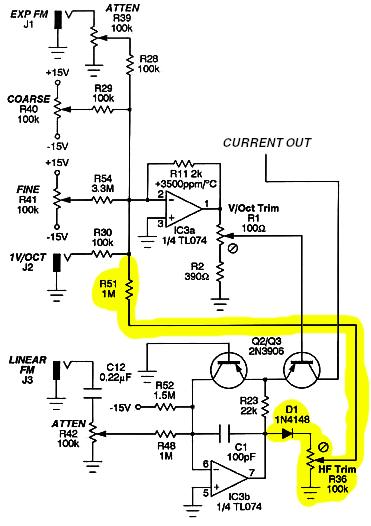
The voltage at the output of the servo op amp is proportional to the input control voltage, therefore logarithmic in output current and frequency. At low operating frequencies, thus low output currents, the base-emitter voltage of the reference transistor will be less than one generic "diode drop" and the diode D1 will not have the chance to pass current. As the operating frequency increases, the base-emitter voltage will increase logarithmically, and D1 will start to turn on, though the current actually flowing through it will be quite limited by the voltage drop across the trimmer R36. The point is that the top of R36 will be a voltage of basically zero except in the highest part of the frequency range, where it will start increasing slowly with frequency. An adjustable fraction of that voltage is coupled through the 1M resistor R51 back into the input amplifier. So: at low frequencies, the HF trim circuit will have no effect. At high frequencies, it will push the frequency even higher by a small and controllable amount. That's what we need to counteract the nonlinearity of the oscillator core's current response. It's easy to imagine that if increasing frequency causes the frequency to increase further, it could cause the whole thing to go out of control and lock on the maximum frequency; but in fact, the gain around this feedback path is so low that it's not able to do that. It only bends the curve upward a little in the high-frequency range.
For completeness I should mention the linear FM circuit, which I edited out of most of my other diagrams but is shown on this one. It works by fudging the reference current in the transistor pair: a voltage on the linear FM input pulls extra current through the reference transistor or removes some, and since the output current is defined as a multiple of the reference current, this automatically scales the output current as desired. This input is AC-coupled with a capacitor to prevent DC offsets on it from screwing up the calibration of the rest of the converter. This is a pretty standard way to do it in analog exponential converter circuits, and it could be easily omitted in a design that didn't require a linear FM feature. Note that this basic linear FM input cannot do "through-zero" modulation; if one applies enough voltage to reduce the reference and therefore output currents to zero, they won't go to less than zero. The exponential converter will not start sinking current in the opposite direction, and the VCO core will not run backwards. Implementing through-zero linear FM requires more elaborate design of both the exponential converter and the oscillator core.
I've described the operation of a typical real-life exponential converter, starting from an oversimplified toy circuit and then adding each layer with some intuition on why it's needed. Circuits of this kind are found in very many synthesizer designs and it's worth having some understanding of how they work.
◀ PREV Level up on circuit simplification || Updates and new module development NEXT ▶
MSK 015 Quad VCA
US$431.78 including shipping
Comments
I'd rather use germanium transistors in distortion circuits, which often benefit from their lower gain and less-sharp clipping.
It's in a SOT-23-6 package, which is a LOT easier to solder than the microscopic SOT-363 that the PMP5401Y comes in.
I've been working with a triangle core lately, so I'll also have to try out its sister DMMT5551 for the current mirror on the negative side, probably bootstrapped with a regular MMBT5551 in a Wilson configuration - the match on the third transistor isn't that critical. On the other hand, as the design progresses, I might find myself with half a LM13700 and abuse that for the purpose (if I use the other half as a sine shaper).
I don't know yet how it'll perform in circuit, but plan to check it out (with a tiny platinum RTD expoxied to the back of the device, and a bit of closed-cell foam packed around it to protect from air currents).
I would not expect it to be the same between NTC and PTC tempo/thermistors because they use very different underlying technology. I think PTC type are usually, basically, metal wires (platinum, as Schmitz said). Low resistivity so you need a long wire to build up enough resistance to be useful. If that wire were coiled then it'd look like an inductor and that might be a source of significant inductance. NTC thermistors of the kind I'm accustomed to are basically lumps of solid ceramic - the resistivity is high and so they need a short, wide path for the current in order to create a low enough overall resistance. That's not a physical design that would lead to significant parasitics and I would expect their behaviour to be close to that of ideal resistors. But I haven't tested this except implicitly by the fact that I've been building circuits on the assumption they are close to ideal temperature-sensitive resistors, and the circuits work.