Level up on circuit simplification
2018-09-22 electronics math
In my last entry I talked about the rules for simplifying series and parallel circuits. Two resistors in series can be replaced by one with a value equivalent to the pair of them; two in parallel can similarly be replaced; there are other rules in the same general form for capacitors and inductors (assuming theoretically perfect components); and by applying these rules repeatedly you can simplify complicated circuits down to much simpler equivalents. I also set up an interactive reverse calculator for finding combinations of standard-value components to make up a desired, maybe non-standard, value.
The rules for series and parallel components will take you a long way, but there are some circuits that can't be analysed that way. For one thing, if a circuit involves more than one kind of component, such as both resistors and capacitors, then it may not have a simple equivalent value; the behaviour of such circuits can depend in a complicated way on frequency. That is, after all, a big part of why we build such circuits: they are the basis for filters and many other things.
However, at any fixed frequency, it's possible to simplify any arbitrary two-terminal network down to a single resistance and either a capacitance or an inductance, and you can do it by applying the rules for resistances alone, but treating them as impedances: complex numbers with real and imaginary parts. Convert the capacitances and inductances to their pure-imaginary impedances for the desired frequency, use complex-number arithmetic throughout, and it works. I won't go into that further here. Instead, I'd like to talk about the cases where the basic topology of the circuit - even using plain resistors alone - does not allow for series/parallel simplification.
Circuits that are not series-parallel
Some circuit topologies cannot be expressed as series and parallel combinations of components. The "bridge" topology is a classic example.
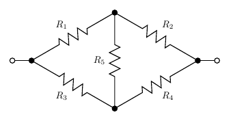
The bridge circuit contains no series or parallel resistor pairs that we could analyse with the rules of series and parallel circuits. And yet such circuits can certainly be built, and we could build one and attach an ohmmeter to it and get a reading. We ought to be able to predict what that reading will be. How?
If the five resistors are all the same, or more generally if R1/R2 = R3/R4, then the pairs R1 and R2, and R3 and R4, function as voltage dividers with identical ratios. Then the two ends of R5 will be at the same voltage, no current will flow through it, and then we can remove it entirely or replace it with a short circuit, and either way the bridge turns into something we can analyse with the series and parallel rules.
This principle of spotting nodes at equal voltage becomes important for the cube question I'll describe later; and it's worth mentioning that in practice, bridge circuits often are designed to balance, with no or almost no current flowing through the centre, anyway. This circuit topology dates back to the 1800s, when a common way of measuring component values or physical quantities that were sensed by variable component values, was to put the unknown value into one side of the bridge and adjust known resistances on the other side until there was no current flowing through the centre. The basic bridge used for this purpose was called a "Wheatstone bridge" (for Sir Charles Wheatstone, 1802-1875, but actually invented by Samuel Christie); it is indirectly an ancestor of the Wien bridge oscillators used in the North Coast Synthesis Fixed Sine Bank.
But if the two sides of the bridge do not implement the same voltage division ratio, we seem to be stuck. There are no two resistors in series without something else connected to the node joining them, so we cannot apply the series rule; and there are no two resistors in parallel, so we cannot apply the parallel rule.
The answer is to introduce a new rule, which goes by several names but is often called the delta-wye transformation.
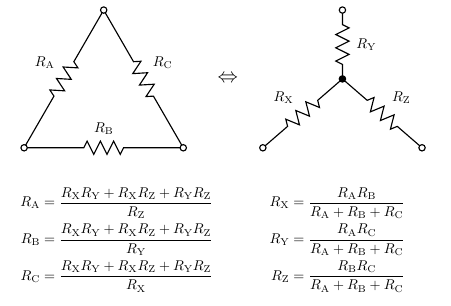
Where three resistors form a triangle, that's called a "delta" (for the Greek letter Δ) and we can replace it with three other resistors forming a "wye" (for the Latin letter Y). Similarly, any wye can be replaced by a delta. Applying this (in either direction, in fact) to the bridge circuit results in something which can be simplified further using the standard series and parallel rules.
The famous resistor cube
The famous resistor cube is a traditional "brain teaser" question. Some people think it makes sense to ask this during job interviews, or on exams in school. It seems to be quite popular in India; I don't know the Indian educational system but it seems like they have some kind of national standardized tests and the resistor cube comes up in those a lot, so there are very many videos online of people explaining how to answer the resistor-cube question specifically for passing the Indian tests. And so, of course, everyone just memorizes the answer and it's completely useless for testing anybody's problem-solving skills. Note, also, that when Google did their study on interviewing, they found that brain-teasers just don't work. They're more a matter of testing the applicant's cultural background and making the interviewer feel smart themselves. Ability to answer brain teaser questions has nothing to do with actual success once hired.
So with that in mind, let me give you some hints and spoilers: the bear was white; 90 minutes is exactly the same as an hour and a half; the surgeon was the patient's mother; the detective committed the murder himself; fill the ship with ping-pong balls (this one was the plot of a Donald Duck comic); "in the dictionary"; cut the cake along the X, Y, and Z coordinate planes; and the one about the rubber gloves is easier to memorize if you think of it in terms of condoms instead. As for the resistor cube, see below.
The problem as it's usually stated is that the twelve resistors along the cube edges have 1Ω resistance each and you're supposed to find the resistance between two diagonally opposite corners, such as from the corner labelled A, to the corner labelled D.
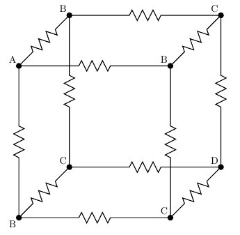
As I mentioned, what people really do is they memorize the answer: 5/6Ω. The traditional "right" answer is to recognize points of equal voltage, as I mentioned doing with the bridge circuit. Remember that we're attaching the ohmmeter probes to A and D. When that's the case, all of the three nodes marked B are at the same voltage, by the symmetry of the cube. Although there are no resistors directly between nodes marked B, we could put some in and they would have no effect. We could also short them directly together. Similarly, we could short together the three nodes labelled C, which are at equal voltage. And having done that, we've reduced the cube to a series combination of parallel combinations of 1Ω resistors: three from A to B, six from B to C, three from C to D. That makes 1/3Ω + 1/6Ω + 1/3Ω = 5/6Ω, which is the right answer to the question.
If someone wants to make the question a little harder, they'll ask for the measurement across a different pair of nodes in the cube. Diagonally across a face of the cube (from A to one of the nodes marked C), the resistance is 3/4Ω, and along a side (from A to one of the nodes marked B), it's 7/12Ω. I won't draw diagrams of the detailed calculations, but they come down to the same procedure of recognizing equal-voltage points and then doing series and parallel simplification.
The next step up in difficulty would be to give the resistors in the cube different values. Then it's no longer possible to use symmetry to change the cube into a series/parallel network. If somebody pulls that on you in a job interview you should perhaps think about whether you really want to work for such a smart alec, but be that as it may, it's possible in such a case to work out the result with the delta-wye transformation.
Going further
Is this the last word on simplifying resistor networks? With the delta-wye transformation as well as the series-parallel rules, can we solve every resistor problem?
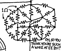
At first glance, it might seem that we can. Even very difficult-looking networks, like this one from an XKCD cartoon, succumb to delta-wye analysis. The answer for this network is 25265/33783 or approximately 0.74786Ω.
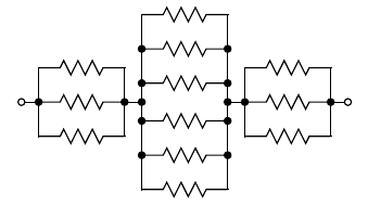
But the correct answer is "no." In fact, it is possible to construct resistor networks that cannot be simplified by series, parallel, or delta-wye transformations. We don't often see them because it takes a lot of resistors to build such a thing, and such complicated resistor networks do not actually occur very often in practice. In graph theoretic terms, what it takes for the series, parallel, and delta-wye rules to all be inapplicable is that the resistors should be along the edges of a graph that is simple (no multiple edges; prevents parallel-resistor simplification), triangle-free (prevents delta to wye simplification), and has minimum degree 4 (prevents series and wye to delta simplifications). For example, this circuit - which is the one with fewest resistors meeting the conditions. It corresponds to the graph called K4,4: two sets of four nodes with a resistor connecting each pair of one node from each set.
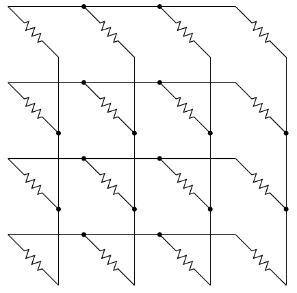
You can check for yourself that that meets the conditions: there's nowhere in it that the series, parallel, or delta-wye (in either direction) rules could be applied. Another example would be the four-dimensional hypercube graph I've used for automated composition.
There is such a thing as a star-mesh transform, which can be applied to any resistor network to eliminate one node (at the cost of quite possibly adding many new resistors), and by applying that and the other rules a sufficient number of times it's possible to simplify any two-terminal resistor network down to a single equivalent resistance. However, it's quite cumbersome to do because of the skyrocketing number of steps as minimum degree increases. Really, at this point when confronted with a circuit for which the simpler rules don't apply, it makes more sense to just throw the whole thing into a circuit simulator with a constant current applied between the appropriate points. Then you can read off the equivalent resistance as the resulting voltage drop, suitably scaled. See my Free EDA Software rundown for more about circuit simulators.
The way the circuit simulators do their job comes down to applying the basic rules, Ohm's and Kirchoff's laws, to create a set of simultaneous linear equations. The usual form, called nodal analysis, assigns a variable to the voltage at every node. Then it's easy to express the current through each component by Ohm's Law on the voltage drop, and the net current at each node must be zero except where current sources or sinks are attached, so that gives the equations. Numerical matrix algorithms are applied to solve the set of linear equations. There are some subtleties having to do with careful management of rounding-off errors and so on, but it's all fairly well-understood computer science.
So, I've described in my earlier entry the basic rules for simplifying series and parallel circuits. Not all circuits are series or parallel, so I've described in this entry some of the ways that approach can fail, and presented some rules for simplifying more complicated circuits, including the famous resistor cube. Even these more advanced rules are not absolutely universal; when they too break down it's usually best to abandon hand analysis and run a computer simulation instead, but I've talked a little bit about how the computer simulations work and how one would go about doing it by hand if determined not to use computer simulation.
◀ PREV Combining components for new values || Exponential converters and how they work NEXT ▶