Inrush current and measuring it
2023-10-18 electronics science!
Sometimes I get questions about what the questioners call the "inrush current" of North Coast Synthesis modules. I think people who ask about this are usually hoping I can give them a single number in answer - "The inrush current of X module is Y number of milliamps" - and then they'll be able to compare it against some specification of a power supply and know whether it'll be safe to connect that module to that power supply, or compare it against other modules to decide which one is better and which one to buy. Maybe they think it would make sense to compile a spreadsheet or start a "List of module inrush currents 2023" forum thread. Unfortunately, inrush current isn't as simple as that. No simple answers are possible, and attempting to reduce the matter to a bare number per module is counterproductive. Let's look at the issues in more detail.

Inrush current and why it exists
Electronic circuits are usually designed around their normal operating states. When something like a synthesizer module is powered up and doing whatever it does, in its usual way, it will draw a certain amount of current from the power supply. Many things are understood to be true in this normal operating state like "the power supply voltage is its normal value and not in the process of changing to some other value" and "all the bypass capacitors are charged to the power supply voltage" - and the circuit design is based on the assumption that these facts are true.
But these facts are not always true. Sometimes in real life the circuit will be powered down, with the supply voltages all at zero and the capacitors fully discharged. And then when you turn it on, it will briefly go through an intermediate state of being neither off nor on, when everything is changing, as the power supply voltages start to increase toward their normal values, the capacitors are charging up, wires that will carry current in normal operation are just starting to become active, magnetic fields are being formed, and so on. Something similar happens in the other direction during power-down.
Designers are aware that the circuit will go through this kind of intermediate state, and they plan for that, but it is far from the normal operating condition of the circuit. In the intermediate state during power-up, it often turns out that what happens is the circuit draws far more current than it will in its normal operating state, just for a few microseconds to milliseconds before the current draw settles down to normal. I mentioned "milliamps" at the top of this article as the units in which the people who ask about inrush current want an answer, but if you could really measure the peak of the inrush current for a typical synth module (which is not easy, as discussed below), I think it would often be measured in amps: multiple thousands of milliamps and way above the continuous-output milliamp rating of a typical synthesizer power supply.
Nonetheless, real power supplies are usually able to support real modules in practice, even during power-up, and that is because supplying a brief spike of high current during power-up is very different from supplying a continuous load at that same high current value during normal operation. Power supplies are designed to, and can, power real loads. It's not usually a problem for the peak of the inrush current pulse to greatly exceed the much lower continuous rating of the power supply. Something similar can be said about things like wires, which might be rated for only one or two amps in normal operation but might carry a burst of much more than that for a short time during power-up, without harm. The mechanism for them to be damaged by high current only comes into play on much longer time scales.
The main mechanism for inrush current to occur in modern solid-state circuits is through charging of bypass and filter capacitors. Many circuits tend to draw power in bursts; for instance, the MOSFETs in CMOS logic draw tiny but sudden pulses of current that last nanoseconds or less, every time they switch between states. It is difficult for a power system to provide those bursts of power across any significant distance - even a few centimeters - and so the usual practice is to put capacitors in parallel across the power lines at frequent intervals all over each circuit board, especially next to the power inlets of ICs, to make sure there is always a capacitor near any component with spiky current requirements. These are kept charged to the power supply voltage and then when a transistor switches and needs a burst of energy, that tiny but fast spike in current is supplied by the capacitor instead of having to come through the longer-distance power lines. Designers often put larger capacitors at the power inlet of each module; the power supply itself will usually also contain other capacitors of its own, larger yet, at its outputs; and in a typical Eurorack power system there may be more filtering capacitors of intermediate size on the bus boards in between the power supply and the modules. Bigger capacitors support bigger but slower changes in current requirements during normal operation.
When power is first applied, all the capacitors need to charge up from zero to their operating voltages, and they will usually charge as fast as the power supply and the wiring will allow. That means a lot of charge is getting from the power supply to the modules in a short time, and that quick flow of charge into the filter capacitors during power-up accounts for most of the inrush current.
Capacitor charging was not always the main mechanism. In the mid-20th Century before solid state was the norm, when electronics meant vacuum tubes, a significant issue had to do with heating up the cathode filaments in the tubes. Vacuum tubes need their cathodes to be hot in order to operate, and they usually contain tungsten filaments like incandescent light bulb filaments, which are heated white-hot during normal operation and keep the nearby cathodes hot. When power is turned off, the filaments are at room temperature, and they must heat up when the power comes on. But it's a fact about tungsten filaments that they have a high positive temperature coefficient of resistance: at low temperature, they have low resistance and draw much more power from the same voltage. So a power system that is supplying the filament power for vacuum tubes will see a much higher load during power-up while the filaments are heating, than will be present in normal operation; and this initial current spike will have a different time profile from what we see in present-day solid-state circuits, because it lasts for the probably-longer time during which the filaments heat up.
In large systems that are more described as "electrical" or "electromechanical" than "electronic," there can also be other physical mechanisms that cause inrush effects. Rotating machines may need to spin up mechanical rotation; coils may build significant static magnetic fields; literal incandescent lamps with filaments, or other things with both a requirement for high temperature and a positive temperature coefficient of resistance, need to heat up; fluorescent lamps and other arc-based things need to strike their arcs; and so on. Most of these aren't relevant to synthesizer electronics.
How inrush current causes problems
It's inevitable with present design techniques that most circuits will require significant inrush current for charging their capacitors, and as I mentioned, power supplies are designed to handle that. So why think about inrush current at all? And why do I get questions about it if things just work? Well, the problem is that it's evident things don't always just work. Sometimes there are problems.
Power supplies and the wiring between them and their loads (such as modules) can be damaged by too much current. A brief burst of high current during power-up is less damaging than the same current would be if it were sustained, because most mechanisms of overcurrent damage take time to happen, a longer time than the duration of the power-up burst. But if the peak is high enough or lasts long enough, or if it happens really often because somebody convinced themselves that per-module power switches were a good idea, the inrush current can cause damage.
More common than actual damage from an inrush current burst, is the scenario where the power supply's protective features successfully prevent immediate damage but interfere with reaching normal operation. It's a fairly common complaint on synth fora that with certain power supplies and modules or combinations of modules, the rack turns on and then immediately turns off, and then keeps turning itself on and off at a frequency of maybe one or two cycles per second. For all the reasons that frequent power-ups may not be good for electronics, this is going to put a lot of stress on the modules and power supply as well as make using the rack impossible.
The "cycling power" syndrome is most often caused by simple overload: your modules require more current in normal operation than your power supply can support, and you need fewer modules or a bigger power supply. But it's also often caused by inrush current, and either way it has to do with the overcurrent protection built into the power supply.
For both safety and business reasons, power supply designers don't want their products to cause or suffer damage when overloaded. Power supply regulators, to do their job, also need to constantly measure and make decisions based on the loads they're supplying anyway. So it is usual for a power supply to include an automatic shutoff feature: if the current goes over a safe limit, the power supply will turn itself off. Even a careless non-professional designer who may be unaware of these issues will probably be using ready-made IC regulators which have such protection built in, so they end up with at least some level of overcurrent protection unintentionally. The shutoff limit will usually be safely below the current level that would cause damage, or at least below the level that would cause serious and dangerous damage, so the automatic shutoff protects both the power supply and the load from harm in case of overcurrent. In the short term, overcurrent becomes an annoyance rather than a danger.
It can happen that the normal operating current of the load is within what the power supply could support, but the peak inrush current - and more importantly, the time profile of that current, how long it stays above different levels - is such as to trigger the power supply's overcurrent protection. When inrush rather than normal operating current triggers the protection, then because it's transient the overcurrent is gone almost before the supply begins to switch off. So it may not switch off every time, or it may not even switch off completely. But if the supply switches off and then switches on again as the overload disappears, that's another power-up, and possibly causes another pulse of inrush current, so the system can get locked in a repetitive cycle of switching on and off. And because the inrush current is transient, it may be difficult to debug the problem. Measurements of the steady-state current draw of the modules in conditions where they operate normally, will not reveal what's happening because such measurements suggest there is no overload; and measuring the amount and the exact time profile of the inrush, without invalidating the measurements by changing the experimental conditions, may be difficult.
"It depends"
If too much inrush current is a problem, and some modules draw more than others, and some power supplies can handle more inrush current than others, then why can't we just have standards for this? Every module should have a specification for how much inrush current it requires and every power supply should have a specification for how much inrush current it can provide, and then we could easily predict which module/power combinations would or wouldn't work.
It's amazing how eager non-manufacturers are to tell manufacturers what we ought to "standardize" - and if a manufacturer makes the mistake of answering questions with numbers, it's amazing how quickly the numbers will end up in somebody's spreadsheet and "list of" thread with all the important context stripped away.
The problem is that the only honest short answer to a question about how much inrush current a module requires or a power supply can provide, is "that depends." The truth won't be a single number. It really does depend - not only on the module and the power supply, but on the wiring and power distribution stuff between them, and everything else in the system; on what variable, exactly, you think you are measuring; and on what equipment you use to measure it. Everything attached to the power rails is interacting with everything else during the time that the system is powering up. The same module will end up drawing different amounts of current during power-up, for different amounts of time with a different profile of how the current draw ramps up and down, depending on everything else in the system.
A theoretically ideal capacitance suddenly connected to a theoretically ideal constant-voltage supply has infinite inrush current. In calculus terms, the current between the power supply and the capacitance is a suitably scaled multiple of the Dirac delta function: it is a thing we can describe by its integral (how many electrons flow during the instant of connection) but not by its instantaneous value (how many electrons flow per second during the zero-second interval when the connection happens).
But note I said "capacitance." What are in a real module are real-life capacitors, not idealized capacitances, and the power supply is similarly not an idealized constant-voltage source that becomes entirely connected within a zero-length time interval. The wiring and other things (such as connectors and bus boards) between the power supply and the module have resistance, inductance, and capacitance of their own - both in the form of explicit deliberately-installed components (none of which are theoretically ideal) and "stray" and "parasitic" effects that are like shadow components not deliberately built into the circuit. Whenever electrons flow through a copper wire they encounter some resistance from the copper itself; as they move they create magnetic fields which then affect themselves and other electrons, resulting in stray inductance; and electric-field interactions with neighbouring wires create stray capacitance. Both the power supply and the module also contain active components like transistors, which may switch on and off and change their behaviour on short time scales in response to the changing voltage and current.
The end result is that the equivalent circuit of a module and its power supply and the wiring in between and the other modules in the system, may be much more complicated than just a switch connected to an idealized capacitance. The behaviour of this complicated system depends on all its parts and changes if any of them change. The peak of the inrush current, and how long it flows and the pattern of how it increases and decreases (which I'm calling the "time profile") change when any part of the system changes.
So even if you could get a detailed description of the inrush current drawn by a particular module in one system with one power supply and one configuration of everything else, it would be different as soon as one of the variables changed. It is not practical to get a complete description of one part's behaviour in all cases, suitable for making predictions of how it will behave in every configuration. The complete description would end up looking like a complicated equivalent circuit that you would then need to run through a simulator, with such circuits for all parts of the system, to maybe get a reasonable prediction of the time profile of inrush current when the different parts are put together. In practice, at most all you can really say is "This module doesn't have much capacitance and is probably going to be okay" or "That one has a lot of capacitance and might be a problem, maybe."
I switched from saying "inrush current" to saying "capacitance" there, and that's a clue: although the peak and the time profile of the inrush current depend not only on the module but everything else in the system, there's at least one relevant thing we can say about a module in isolation that will remain true even as the rest of the system changes, and that is the module's power-filtering capacitance. We can add up the sizes of its power capacitors for a fairly accurate index of how much energy needs to flow into the module during power-up.
To do even better we might multiply each capacitor's value in farads by the number of volts to which that particular capacitor will charge (relevant for circuits with multiple different power voltages), and get a result in units of coulombs representing the amount of electric charge that will have to flow during the power-on surge. One coulomb is equal to the charge of about 6.24×10¹⁸ electrons; named after Charles-Augustin de Coulomb, 1736-1806, France, known for his research on friction and static electricity.

This kind of calculation does not say how much inrush current a given module will really require in any, let alone in every, system, because it tells how many electron charges must flow but nothing about the timing of how long it takes for that many to flow. Two modules could have the same amount of filtering capacitance and very different inrush current behaviour because they have different amounts of inductance and resistance and different active components between the power cable and the capacitors. But at least capacitance is a one-number measurement that depends only on the module and generally, if not always, increases with greater inrush current demand. And some aspects of power supplies' inrush limitations might be approximated by stating them in terms of capacitance too: "This power supply can handle modules with up to X amount of total filtering capacitance."
I still would not advocate numerical specifications for total filtering capacitance or total charge, because of the limitations of such numbers in really making useful predictions. There are too many other variables in play. Power supplies marketed to professional designers (not consumer-level synthesizer users) are likely to state their specifications for inrush current in more complex ways, by actually describing in detail the profiles of current and voltage over time that they can or cannot supply: so much maximum current at all, held for so much time, voltage guaranteed to rise at least this fast and at most that fast, and so on. But even in that market, very much is usually left unspecified.
Measuring inrush current
To make matters worse, even with a clear idea of what behaviour would or would not be acceptable, and a fixed and well-controlled configuation, it's hard to actually measure inrush current.
You can't just put a multimeter on "amps" range in series with the module, as you might to measure normal operating current; the current changes too fast during the power-up inrush to get a measurement of the height of the peak or its timing. Blink and you miss it. You really want to use a digital storage oscilloscope that can capture and save a recording of how the current changes in detail over time during the inrush. But most oscilloscope probes only measure voltage, not current. All right, so then you might put a resistor in series with the module power and use the scope to measure the voltage across the resistor, which will be proportional to the current by Ohm's Law.
It had better be a very small resistor, because otherwise it will change the way the module and power supply interact with each other. And then the voltage you're measuring with the oscilloscope will be small too. Oscilloscopes don't usually work well on voltages less than a few tens of millivolts, and then to measure a current on the order of a few amps, the smallest series resistor you can use will be at least a few milliohms, which is significant compared to the resistance in a good modular power system, large enough to risk disruption of the inrush current behaviour that you're trying to measure.
Having dealt with the low voltage issue somehow, you may next run into a technical problem in that most oscilloscopes have a hard connection between the mains ground and the ground side of the voltage probe; so if any part of your module and power system under test also have such a connection, then you can only measure the voltage between a point and ground instead of the voltage drop across a resistor in series with a nonzero power voltage. Even when measuring a grounded resistor you may create a "ground loop," which will receive via induction a significant amount of interference at the mains power frequency (50 or 60Hz); and because you're looking at such small voltages, even a little bit of that interference may screw up your measurements.
Instead of using anything connected in series with the power system, what would be really nice for measuring inrush current with an oscilloscope would be a special kind of probe that makes a magnetic and not an electrical connection to the wire under test. It clips around a wire and then measures the magnetic field of the current in the wire. That eliminates the ground-reference issue and doesn't directly add any series resistance. It will increase the wire's inductance, and may indirectly increase the resistive component of the impedance; we can hope those things will happen only by a negligible amount. In fact the effect is a lot like putting a ferrite bead on the wire.
But there are further issues to resolve, because the simplest, passive, kind of magnetic current probe is basically just a transformer using the wire under test as a less-than-one-turn primary. Like other transformers it only works on AC current. When measuring a module's inrush current you want to measure a changing but unidirectional current, including the absolute DC component of that current. Since the DC component of the current is unchanging, the transformer cannot pick it up. DC current calls for a more complicated probe containing battery-powered active electronics and something called a Hall effect sensor (Edwin Herbert Hall, 1855-1938, USA) which can measure static magnetic fields.

But seriously, measuring inrush current on a Middle Path
Despite the difficulty of doing inrush measurements accurately in a realistic environment, and comparing them between different installations, I thought it would be fun to try, and I bought a magnetic current probe through AliExpress. This is a Hantek CC-65. It clips around a wire, forming a magnetic instead of electrical connection, and it plugs into the BNC input of an oscilloscope where a more conventional probe might. Battery-powered electronics in the probe measure the the magnetic field around the wire under test and present a voltage to the oscilloscope input that is supposed to be proportional to the current through the wire, at either 10mV/A or 100mV/A.
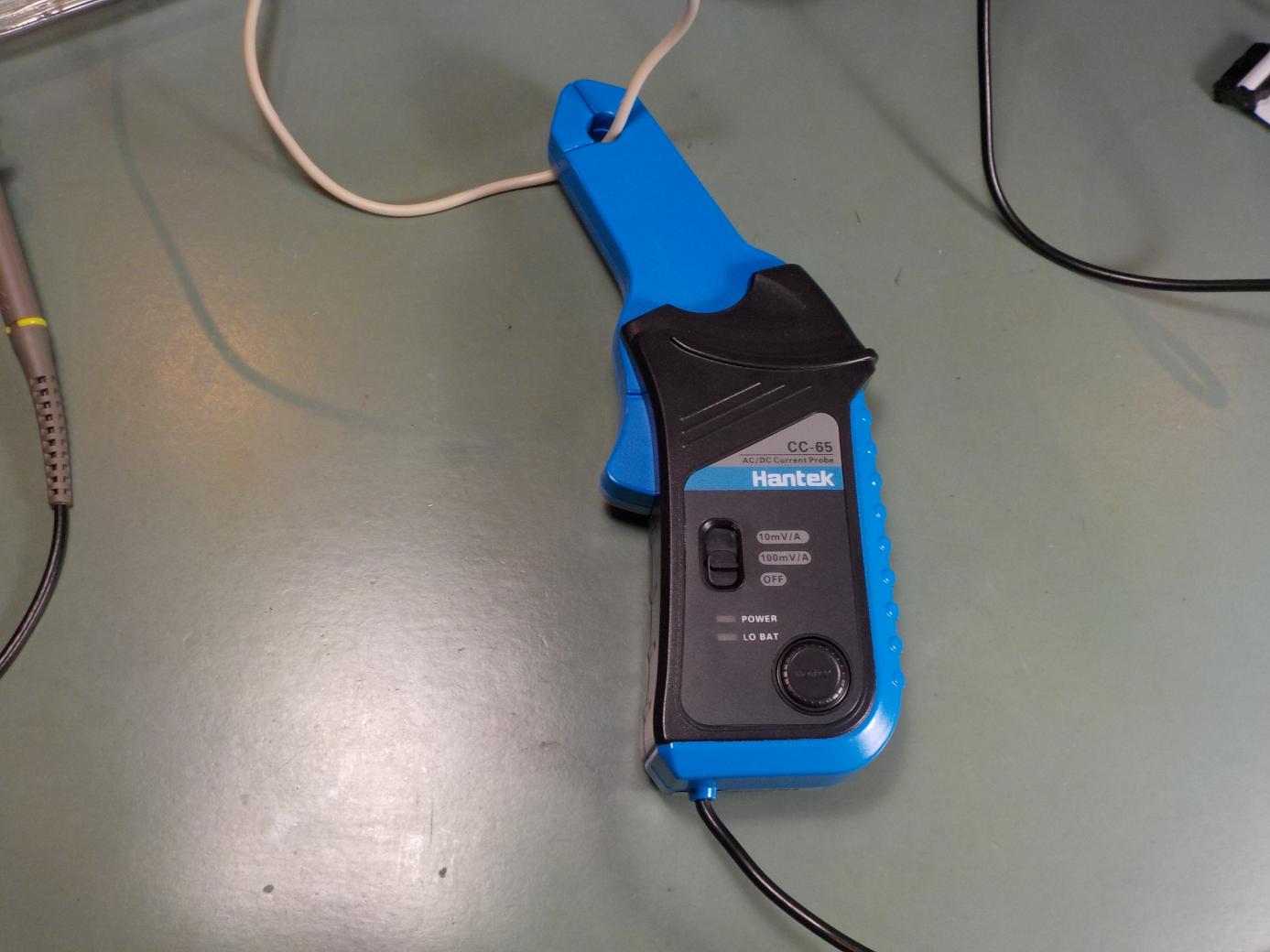
There's a "zero" button which needs to be pressed at zero current to zero-reference the output. Otherwise, interference from static magnetic fields like the Earth's, and hysteresis in the probe's steel core, will result in a voltage offset on the output, which is worse on the more sensitive range. In practice it's something like taring a weight scale.
The probe is claimed by its manufacturer, Hantek, to be good for currents up to 65A (on the less-sensitive range, which I was using) and frequencies up to 20kHz. That may be an issue, because in some of my measurements it produced output that seemed to significantly exceed those limits. I think the manufacturer was conservative in stating their product specifications, and it actually does work somewhat beyond its claimed limits, especially with respect to frequency (there is evidence of that below) - but maybe beyond the limits it does not work at the 1.5% accuracy they claim for better-behaved signals. They do make another probe claimed to be good for higher currents, but when I was shopping I didn't realize how high the measured currents would actually turn out to be, and I thought 65A would be plenty.
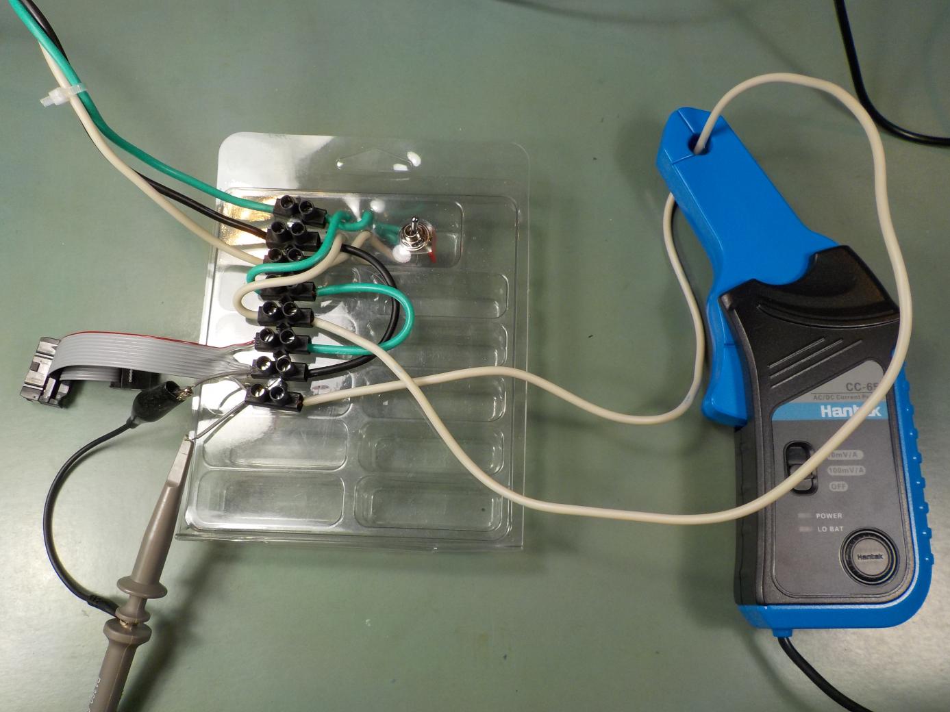
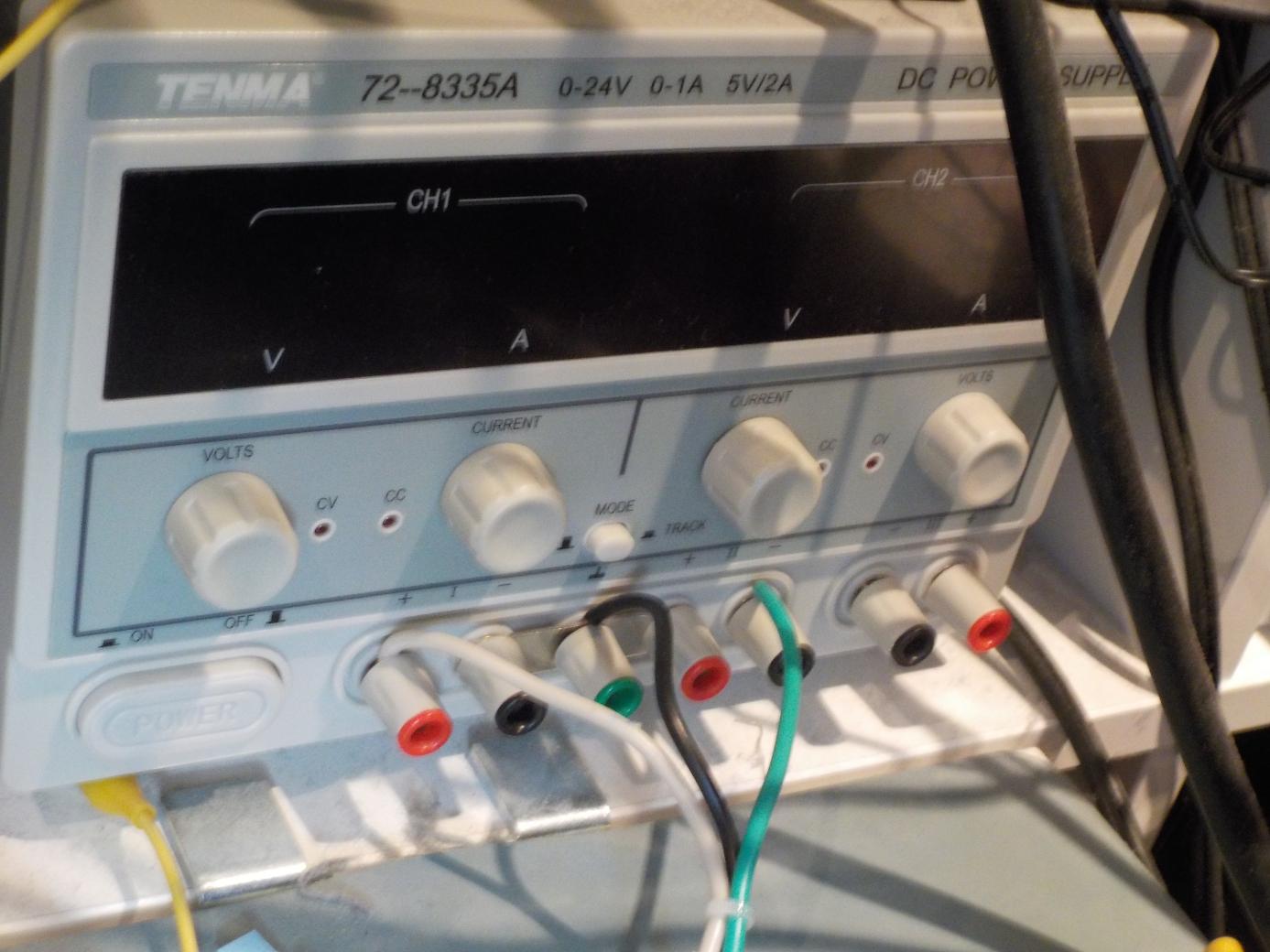
I rigged up a test jig consisting of a Eurorack power plug with the positive and negative rails run through a DPST toggle switch (actually one side of a DPDT) and a terminal block and some wires running back to the binding posts of my lab power supply, which is a Tenma 72-8335A, a fairly typical Chinese-made benchtop unit. The connections are all made with heavy-gauge wire, and the positive rail goes through a loop on which I can clip the probe. I also attached a voltage probe, for the other channel of my oscilloscope, directly to the positive and zero rails, to have a way to trigger the scope. The general idea was that I wanted to keep the impedance low and give the module under test the chance to draw as spiky a surge as possible.
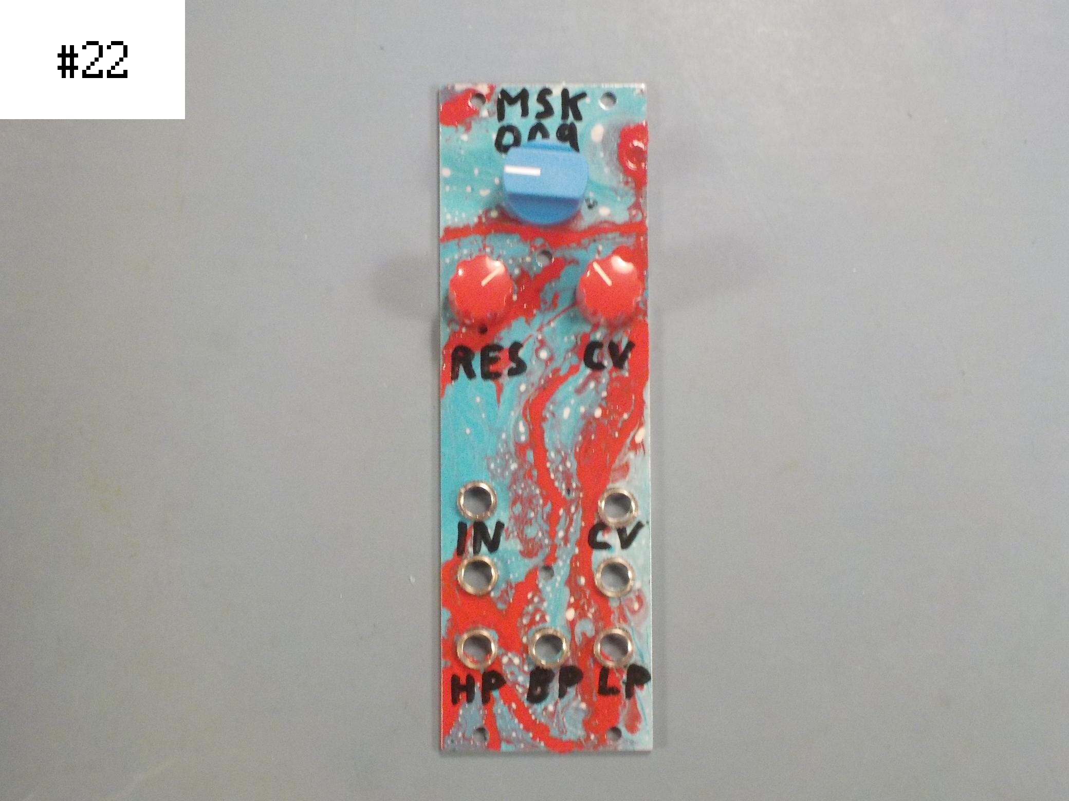
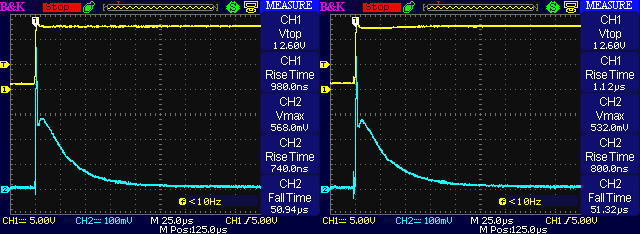
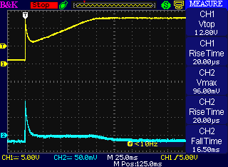
Here are four shots of powering up the +12V rail on a North Coast Synthesis Ltd. Middle Path VCO in the test jig as described, by flipping the toggle switch to connect the module to the already powered-up power supply. The yellow trace at the top is voltage measured with a standard oscilloscope probe, used as the trigger for the scope. The cyan trace at the bottom is current measured with the magnetic probe, on a scale where 10mV corresponds to 1A and so each square of the oscilloscope's 100mV-per-square display represents 10A. If we are to believe the oscilloscope's automatic peak measurement, then the highest point of the power-up surge is about 75A (that is 75000mA) every time.
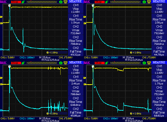
Are these measurements really accurate, and do they reflect what would happen if the module were actually installed in a Eurorack system? Probably not!
First of all, note that 75A is greater than the probe's maximum rating of 65A. It's quite understandable both that the probe's output amplifier, designed to produce a voltage of between 0 and 0.65V for the scope to display, might have a little bit of headroom and actually work at a little more output voltage; but it's also understandable that it wouldn't be designed with a lot of headroom. So when it gives an output voltage of more than 0.65V as shown on the scope, we can reasonably interpret that as meaning "a lot of current, more than 65A, but not accurately measurable."
Second, the probe is specified as working with frequencies up to 20kHz, at which frequency one cycle lasts 50µs. The narrow spike in the apparent current is much narrower than that, less than 5µs, and the entire power-up surge fits in 50µs. So if we believe the narrowest spike is really just what it appears to be on the scope trace, then we are believing that the probe works accurately at more than ten times its stated maximum frequency. More plausible is that that spike is not exactly real; it just indicates some high-frequency stuff is going on that the probe cannot accurately measure.
The most important reason to disbelieve these measurements is that my test jig is not what real Eurorack power systems look like. In a real power system, the switch is not usually between the power supply's DC output and the module's DC input. The power switch in a real system is upstream of the power supply's AC input.
Here's another measurement, in which I used the same test jig but left the toggle switch turned on and started with the power supply's own switch (which is on its AC input) turned off. Then I turned on the power supply with its own upstream AC power switch, so the entire power supply including its heavy toroidal transformer was coming up as the module came up. This would more accurately reflect how most Eurorack users really turn on their systems.
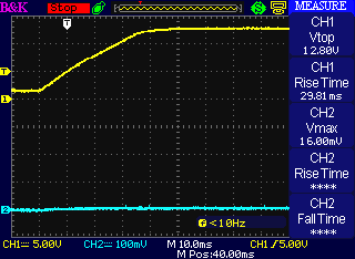
Note I had to use a much longer time scale to even see the startup process on the scope when switching the power supply's AC input. The Tenma power supply takes 30 to 40ms to ramp up its voltage from zero after I hit the switch; that is roughly a thousand times the duration of the surge observed in the earlier tests where the switch was on the DC rails. The current trace is flat in this test. If it jogs up a tiny bit during startup, showing the module's steady-state current of something like 70mA, that jog is pretty much lost in noise at this vertical scale. And this is the more realistic test case as far as simulating what happens in most real Eurorack installations. In the realistic scenario, people flip the switch on the AC power input and there's not really any startup current surge on the DC side at all, only a ramp up.
Nonetheless, despite probably being inaccurate measurements of phenomena that may be really happening in the test jig but wouldn't necessarily happen in a real system, the switched-DC measurements certainly look exciting. And I wanted to write a Web log entry about measuring startup surges, which I can't do in a test configuration where there are no surges to measure, so I'm going to try to learn whatever I can from the switched-DC test setup even with its inaccuracies.
The Tenma power supply has a substantial filtering capacitor (probably a few hundred µF; I think I saw a schematic for it once but I do not have the schematic at my fingertips now) right behind each of its outputs. The Middle Path has a 10µF filtering capacitor on each of its power inputs, behind a Schottky protection diode. There are also about a dozen 0.1µF decoupling caps per rail, and on the positive rail we're measuring, there is a 9V regulator with a second 10µF capacitor on its own output. All in all we need to charge up about 21µF of capacitance from the +12V rail during startup. The diode, the mechanical toggle switch, and the wiring of the test jig (with the current probe clipped around one of the wires) are the only things between the Tenma's output capacitor and most of the capacitance on the +12V rail inside the module, including in particular the 10µF input filter.
So when the switch closes, all that's between those two capacitors is the diode and the resistance and stray inductance of the wiring. The big capacitor is charged to +12V; it won't discharge much in a few tens of microseconds; and the little capacitor starts out fully discharged. There's a 12V drop imposed across the wiring, switch, and diode in a fraction of a microsecond. If 75A flows at that instant, it implies the total resistance of the wiring and stuff (probably including some inductive reactance) is about 0.16Ω - which is quite plausible. If it's really a little more current because the probe doesn't go that high, then the resistance may really be a little less but not drastically less - which is again, quite plausible. Then from the scope trace it looks like the current drops off exponentially as the capacitor charges, which again seems like what we'd expect for one cap charging from another through a resistance and not much else.
Looking at the cleanest of the four examples, I estimate that the area under the current curve is about five and a half squares on the scope display. Each square is 10A by 25µs, or 250µC, for a total of 1375µC. Note the units: a µC is a "microcoulomb," the charge carried by one microamp in one second or one amp in one microsecond. Charging the module's capacitance of 21µF to 12V (bearing in mind the power wasted in the 9V regulator, so charging the one cap that goes to 9V is really like charging it to 12V from the input point of view) should require 252µC, so the surge is a fair bit bigger than we might expect from theory if the startup current were only charging the capacitors and not doing anything else; but of course there are many sources of error to contend with here.
What about the shapes of the curves, and the weird spikes and stuff in most of them? I think there are a few interesting points to note there. First of all, I think the narrow spike (a few microseconds by at least 40A) at the very start of each test, followed by a dip and second peak, is associated with the inductance in the test jig, much of which is probably created by the magnetic probe itself. We have an RLC circuit with a resonant frequency that seems to be in the hundreds of kHz, and a damped oscillation that fades out over maybe one and a half cycles when that resonant circuit is hit by the very fast transient of the suddenly-applied voltage.
Where there are additional spikes later in the startup surge, I think those come from bounces in the switch contacts; they don't always make a clean connection and then stay together, but (especially in the lower-right shot) they sometimes separate again and come together over a space of up to a few milliseconds after I close the switch. That makes the measurements less consistent and less accurate, but on the other hand, people really do use switches just like this one in building real systems, so contact bounce may be a realistic effect we should include in tests - assuming, of course, that we are putting the switch on the DC power line instead of the AC supply input, which is itself not realistic.
I don't think a surge like the one I measured here will really bother anybody. Despite the high peak current which is frankly much more than I expected before I did the tests, it only lasts a few microseconds; and it only exists at all in an unrealistic switch configuration that I built in a deliberate attempt to maximize the height of the peak. Startup surges in most real configurations don't look like this. I still feel okay about hot-plugging modules, which might be the real scenario closest to this test configuration.
Nonetheless, these measurements may be yet another reason not to use per-module or per-row power switches which I hadn't even thought of when I earlier wrote my article recommending against those. If you install power switches per module or per row, on the DC power rails, then to whatever (probably very small) extent a high peak startup current might cause stress, you are maximizing that compared to using a switch on the AC power input. Of course that also depends on other variables including the design of the power supply, but I think it's a reasonable guess that it would generalize to many power supplies.
Measuring other modules
I wrote earlier of the "cycling power" syndrome people sometimes observe, where the startup surges of multiple modules cause the power supply to turn itself off for overcurrent protection, then it resets and tries again, and the whole rack switches on and off at a rate of perhaps a few times per second. That is a time scale of hundreds of milliseconds, or about ten thousand times slower than the time scale I measured for the Middle Path VCO in the worst-case tests above. It seems clear that the Middle Path couldn't be involved in a meaningful way in such a situation because its capacitors do not charge on the hundred-millisecond time scale; but can I find a longer startup surge by testing other modules?
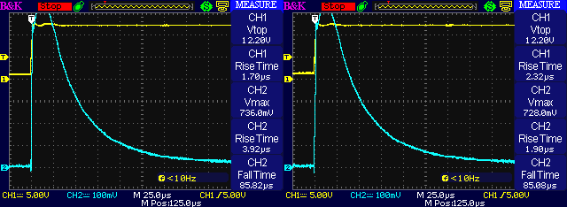
Here are two similar tests on the new MSK 015 Quad VCA. For this and all the remaining tests in this section, I'm using the switch on the DC rails - which is a much more surge-producing configuration than most real installations, but it's what I need to do in order to see a measurable surge at all. These surges look very much like the ones from the Middle Path, which is understandable because the amount of capacitance and the power input circuits of the two modules are very similar.
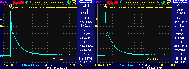
Here are two shots of the MSK 007 Leapfrog VCF, one of them affected by what looks like a bit of switch bounce. It again looks quite similar, understandably, because it also has a very similar configuration of filtering caps and protection diodes.
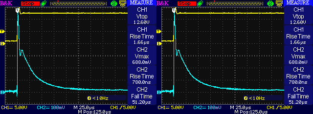
Some people think "digital modules" are especially worrisome with respect to surges, so let's try an MSK 014 Gracious Host.
The surges here actually seem smaller compared to the analog modules, possibly reflecting that there are just fewer chips and fewer decoupling capacitors in this module than in the larger analog modules. It is not more demanding at startup just for being digital. However, this may not be a fair test: I am testing the +12V rail, and this module draws its main power from the +5V rail (which isn't even hooked up in my test jig). We are only seeing the startup surge of the analog parts of the module and not, in particular, the 150µF USB bus filter capacitor. In some future experiment I might rig up a more complicated testing jig to measure possible current surges from the Gracious Host on the +5V rail. A digital module that did not use +5V and drew its main power from the +12V rail might well look different (see below). It is not clear how best to compare modules that do and don't use +5V.
What about modules I didn't design? Here are a couple of shots of an Erica Polivoks VCF, which I built from a kit some years ago. I don't think they sell that exact kit anymore, but similar VCFs are certainly still available. The initial current pulse is larger, probably in proportion to the filtering capacitors, which are 47µF instead of the 10µF in all the North Coast modules. I built the kit with series Schottky reverse-protection diodes and (just for fun) ferrite beads slipped over the legs of those diodes; I don't think that was the default configuration in the kit schematic, which probably did the "resistor or bead" thing.
There's no very visible few-microsecond spike in the Polivoks scope traces and I wonder if that might possibly be the result of the ferrite bead lowering the resonant frequency of the system. The little wiggle in the voltage trace might argue for that happening - it suggests a lower resonance frequency. Or that might only be coming from the larger capacitance. Anyway, the initial pulse is so high that I'm not sure we would see a current spike even if there was one, and this is still all happening much faster than the current probe's rated maximum frequency of 20kHz, so it may not be reasonable to draw any conclusions from the missing initial spike.
I got very interesting measurements from a TipTop Trigger Riot, which is a digital module that draws its main power from the +12V rail, and a fair bit of power at that (manufacturer's safe-side specification 200mA, my power supply indicated 150mA during this test). Note these two traces use an horizontal time scale of 50µs per division to fit the longer surge into the display.
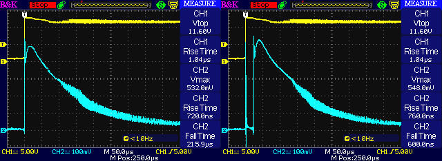
The overall amount of charge in the Trigger Riot startup surge is larger than for most of the modules I tested; my square-counting estimate of the area under the curve comes to about 7500µC (15 squares at 500µC per square, bearing in mind the changed horizontal scale). That is more than the smaller modules showed, but roughly in proportion to this module's higher normal-operation current demand. A reasonable guess might be that it's using 56µF filter capacitors. I didn't disassemble it to look closely at the components in the power inlet, and I don't have a schematic for this module, but I could see without disasembling it that it has some kind of surface-mount electrolytic filter capacitors, and what look like tiny surface-mount ferrite beads (which would have most of their effect at frequencies too high to observe in this test).
The fun part of the Trigger Riot scope shots is that the traces, both voltage and current, go fuzzy about 100µs after power-up. That's a high-frequency ripple, and quite a substantial one. I used different scope settings to zoom in on the start of the high frequency and it looked like this.
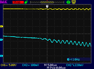
Now if the current probe could be trusted to measure such a signal, the current probe is saying that at this point in the startup process the Trigger Riot's current demand starts to include a component that has a frequency of about 380kHz and amplitude of about 6A peak to peak. I'm counting 9.5 cycles across the last 25µs of the time axis, and a vertical height of 60mV.
We probably should not trust this current probe to accurately measure such a signal; it is only rated for use up to 20kHz! On the other hand, the same frequency starts to be visible in the voltage at the same time, and this oscilloscope and voltage probe are definitely supposed to be good up to 25MHz. I don't think the substantial high-frequency ripple is entirely an illusion created by the current probe. It also is unlikely to be an artifact of my experimental setup because it only appeared with this one module among all the modules I tested with the same setup, and it always appeared with this one module. I think it's clear that the current probe does have some useful response in the hundreds-of-kHz frequency range and it's measuring (if inaccurately) something that really exists, despite that that's far beyond the capabilities advertised by the current probe's manufacturer.
I have not investigated whether the Trigger Riot will continue putting that frequency onto the power rail well after startup. These measurements only cover about half a millisecond, and show that the ripple starts to decrease as the startup surge fades. Maybe the ripple goes away entirely, later. But it definitely seems like something we might prefer not to have on the +12V rail, and it might support the argument that using the +5V rail for digital modules is preferable to designing them to consume all their power from +12V.
Note that even if it's longer than most, this startup surge is still much shorter than the few-hundred-millisecond time scale of the "cycling power" syndrome. It doesn't look like the Trigger Riot would be in much danger of triggering that on a power supply that was not also overloaded for normal operation.
After some experimentation I finally managed to dig up a module with a much longer startup surge: a Pittsburgh Modular OUTS, which I think is discontinued or at least revised by now, but it was part of my first purchase of modular gear years ago. This module has a couple of huge filter capacitors, 1500µF on each rail at the power input. I think those were included as part of an effort (unfortunately not entirely successful) to filter out the significant 120Hz ripple in the power supplies Pittsburgh was shipping at the time. Compare with the 10µF caps in some of the other modules I tested: this one module has as much filtering capacitance as 150 of those other modules!
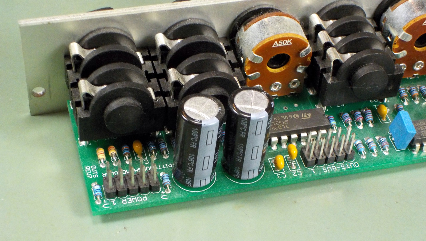
The huge capacitors are behind 10Ω resistors, which will blow out like fuses to prevent more serious damage in case of reverse power connection. The resistors also significantly slow down the startup surge associated with charging the huge capacitors, and help with the ripple filtering during normal operation. I note that the RC time constant of 1500µF with 10Ω works out to 15ms, roughly inverse to the 60Hz North American power line frequency, and that might have been part of the designer's reason for choosing that particular value.
When I power up the OUTS from my Tenma lab supply with my test jig that suddenly applies the DC rails, there is an audible "click" from the lab supply as it briefly goes into and out of current-limiting mode, switching an internal relay. I don't know if changing the current limit might change the shape and timing of the surge, but with the basically random setting it was on when I did one of my tests, it looks like this. Note the different horizontal and vertical scales from my other tests.
The peak current for the OUTS is not all that high, maybe only about 10A. That is much less than other modules, although it is hard to tell whether a higher peak might be going by too fast for the scope to catch it. Most of the surge is at a lower current level. But this surge lasts a long time, about 100ms start to finish, and for much of that time the voltage is significantly depressed. We actually watch the capacitor charging. This surge, even if it has a lower peak, is on the same time scale as the "cycling power" syndrome and if I had a case doing that and containing this module, then this module would probably be the culprit.
Lessons learned
Here's a summary of what I got from my tests with the current probe.
- In my most realistic test configuration, switching the AC power to the lab power supply on and off, I didn't detect surges of inrush current to modules at all, because the power supply ramped up the voltage slower than what would be the time scale of the surge.
- In an unrealistic configuration deliberately designed to make surges look as bad as possible (mechanical switch on the DC rails with a big capacitor in the power supply), I was able to detect some sort of surge into every module in the test.
- Peak current during most surges in this worst-case test was high enough that I felt surprised, and higher than my instruments could measure: over 65A. No typo, that is sixty-five amperes; theory suggests I probably could have predicted it if I'd done the calculation earlier. But I emphasize that this was in an unrealistic worst case.
- Current surge peak height is a reason I hadn't previously thought of, to recommend against per-module or per-row power switches. These switches create a situation that resembles my otherwise unrealistic worst-case test.
- Most surges were fast enough (under 50µs) that the Hantek CC065 current probe's stated 20kHz frequency limit calls into question how accurately it can measure them; however, there is strong evidence that the probe does have some usable response far above 20kHz, making possible at least approximate qualitative comparisons.
- The best predictive factors for size of a surge (both duration and total charge; I couldn't usefully measure peak current) were the size of the module's filter capacitors and whether its power inlet included series resistors.
- Digital or analog did not make a difference to surge size except insofar as it might bear on the module being bigger and drawing more current in general.
- In only one case (the Pittsburgh OUTS, which has unusually large filter capacitors) was the inrush surge of long enough duration that I thought it might be likely to trigger the "cycling power" syndrome in vulnerable power systems. That was 100ms. All others were less than 1ms.
- I observed some unexpected high-frequency behaviour from the TipTop Trigger Riot which I did not explore in detail but which might support the idea that it's preferable to segregate digital modules onto the +5V rail for reasons of interference, not inrush current.
Doing this project cost both money and time, which I can afford only if it attracts customers to buy modules in my shop. After the collapse of all-format sales in 2022, and multiple years of decline in assembled-module sales leading up to that, there is real danger that 2023 may be the last year for North Coast Synthesis Ltd. If you find the work I do valuable and want me to be able to continue, then I hope you will support my ability to remain in the synthesizer business by buying modules in my shop.
◀ PREV Dispensations || DACs and bit count NEXT ▶