The varieties of ribbon cable experience
2024-05-31 eurorack power history
Eurorack ribbon cables are a perennial source of confusion for newbies to the format, and destroying a module by power misconnection has become almost a rite of passage. Many modules, including the ones I sell, include reverse voltage protection to prevent the worst of such mistakes. But rather than write yet another tutorial that expands the simple admonition of "red stripe down" into thousands of words, I'd like to look at some details of the cable assemblies themselves. Have you ever really looked closely at one?
The thing that has two connectors on the ends and plugs into the busboard on one end and the module on the other end, is usually called a cable. That word is what in the study of language is called a common or countable noun: you can have one cable or two cables. On the other hand, the bulk material that comes on a roll and is used to make a cable, is itself called "cable." That's a mass or uncountable noun: you have some cable in this sense, or more cable. It's not easy to keep track of this distinction, so in formal contexts people sometimes use the term "cable assembly" to make clear that they are talking about the countable object as opposed to some bulk "cable." You make a cable assembly out of bulk cable; and I will use that terminology below when it seems clearer than just saying "cable."
Grey and multi-colour
One of the common recurring patterns in electronics is that the pins on ICs, cables, connectors, and other components are numbered, and pin 1 will be marked in some way as a clue to how to number all the pins.
On a DIP IC, there's usually a notch or dot next to pin 1; or sometimes, at the end of the package where pin 1 is (and then you have to know how to find pin 1 in relation to that). Components like electrolytic capacitors and "jelly bean" LEDs will have one leg cut shorter than the other. It's a common practice to make the solder pad for pin 1 of each multi-pin component square or rectangular instead of round. And on 3M grey ribbon cable, by far the most popular brand for Eurorack power these days, there's a red stripe along one edge, marking wire number 1.
On the insulation displacement connectors (IDCs) traditionally used with ribbon cable, there are two markings: a triangle on the housing pointing at pin 1, for humans to see; and a keying bump at a designated location on the side that fits into a corresponding hole on the receptable, so it will plug in only in the correct orientation. On a completed cable assembly, the stripe is one of the most visible features, which is why Eurorack users talk about cable orientation in terms like "stripe down."
It's important to remember that the general rule isn't that there is anything special about the colour red. It's just that there will be some kind of marking for pin 1. You'll sometimes see ribbon cable stock made with other colour schemes, including dark blue or charcoal for wire number 1, and ivory instead of light grey for the others. In all these cases, the one special wire is number 1, no matter what specific colour it is.
When I started out in electronics, it was the 1980s, and I was reading a lot of hobby publications from the 1970s. In those days, digital projects based on microprocessors were just starting to come within reach of the home experimenter. Grey cable existed too and was actually quite popular in the more buttoned-down corporate world, but it's not what I remember. Back in the day, what I remember is that when you had two boards and a lot of signals to connect between them, or something like a floppy disk drive to connect to your main board, you'd use a chunk of rainbow ribbon cable. Like in this Apple 1 clone:
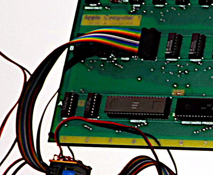
Like some other nominally rainbow things, old-fashioned ribbon cable has a few extra colours in it, and each of the colours has a meaning. In this case the wires are coloured for pin number according to the resistor code: 1=brown, 2=red, 3=orange, and so on up to the tenth wire, which is black for 0. After that, it repeats. So if you have the resistor code memorized, it's easy to keep track of which wire is which as you split the cable to connect individual wires to different things.
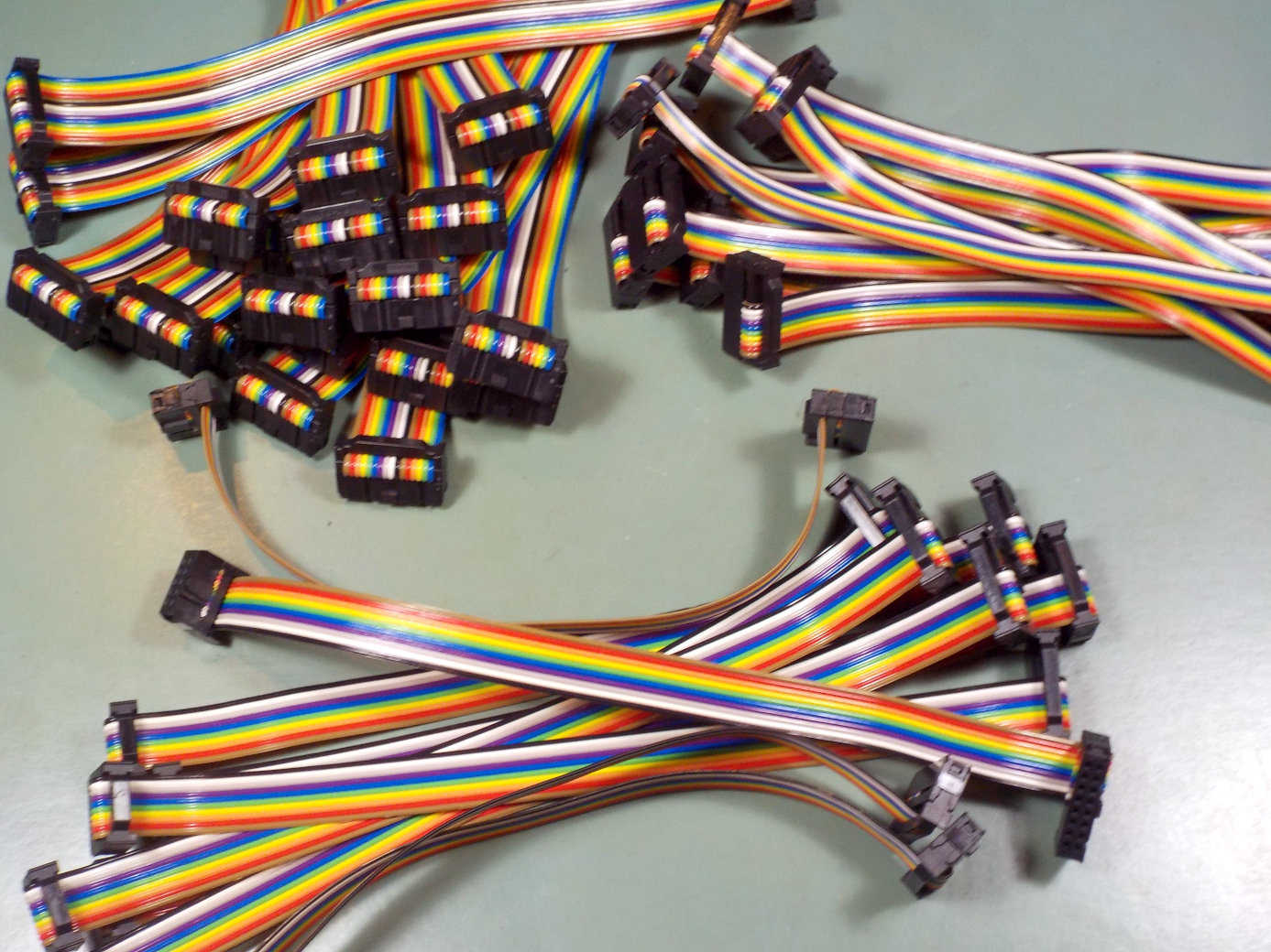
I'm not sure whether multicoloured ribbon cable is a good idea for Eurorack power on a practical level after all. Some people are already quite confused by the idea of "red stripe down," and having a red stripe which is not exactly along the edge, or two red stripes in the case of 16-pin cable, might just be too complicated. But it does look cool, and I didn't have the chance to build as many rainbow-wire projects in the 1980s as I wanted, so I recently bought a roll of multicoloured ribbon cable and made up some Eurorack power cables with it.
I have added both multicoloured and grey Eurorack power cables to the Web storefront as a separate product you can order, inaugurating an "extras" category which may also see some other small products added in the future. So if you want to replace the cables on modules you already have, that's where to go.
There are problems with selling any small item by mail order, largely stemming from the expense of shipping. In order to preserve my "free shipping" offer I had to implement a new storefront feature and designate power cables add-on items, meaning that you can't check out with only a cable in your cart and must buy something else too in order to buy them.
As of July 1, 2024, the special offer of multicoloured cables by default is expired. You can still get them as an "extra" in the storefront but I'm going back to regular cables for regular-production kits and modules.
Number of pins
The Eurorack bus is defined to use 16 pins on the bus board, but the actual number of signals or voltages is smaller because each voltage is assigned to at least two pins (six, for the critical 0V connection). Putting voltages on multiple pins reduces the resistance and improves the current-handling capability, by placing multiple wires and connector contacts in parallel.
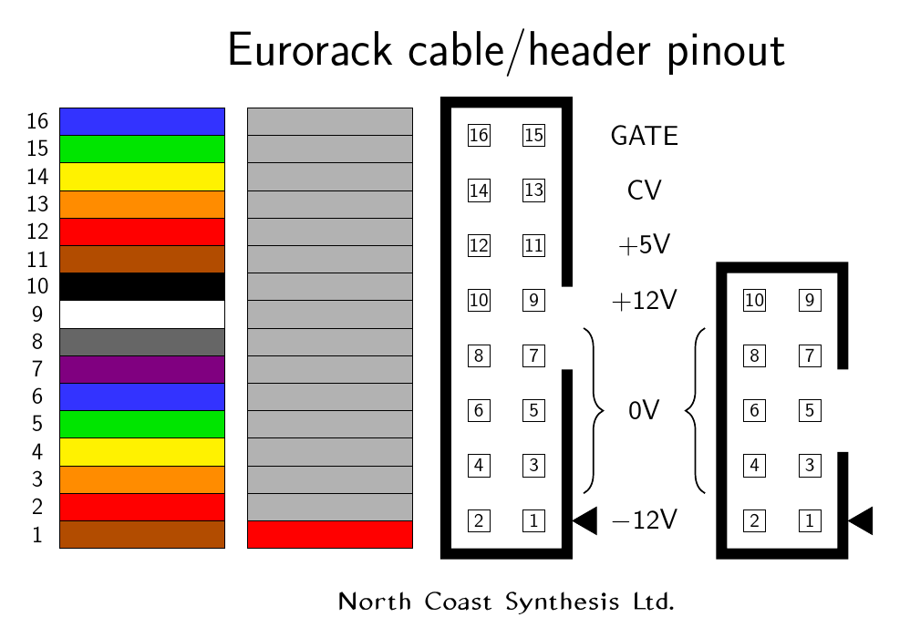
The pinout diagram above shows the headers as they would appear when looking at the board of a module. I have drawn in the typical shape of a "shroud" around the pins, to indicate the slot where the keying plug from the cable-mounted IDC plug will fit; also where the "pin 1" triangle on the plug will land. However, the Doepfer spec recommends strongly against the use of keyed headers (on busboards in particular, with the warning that use of such will void their warranties) because of the prevalance of incorrectly-keyed boards and cables, which make correct connection impossible.
More than keying, I'm interested in the number of pins. There are 16 defined, but everything past pin 10 is sort of optional. Most modules don't use +5V. Doepfer's own specifications page describes the +5V supply as being mostly for "older" modules, which is an interesting characterization given that the main purpose of the +5V supply is to support computer-based digital modules that require a lot of low-voltage power. Treating higher-voltage analog as the "newer" technology may be some kind of wishful thinking. Be that as it may, the other two connections beyond pin 10 are for bus-connected CV and gate, which are features only a few modules support. My own Middle Path VCO is an example of a module that uses bus CV where available, and the Gracious Host requires bus-supplied +5V power, so that it can be passed on to connected USB controllers without polluting the power rails used by audio circuits.
Modules that use all 16 pins of the Eurorack bus require cables that will connect all 16 pins, and those are of straightforward construction.
The majority of Eurorack modules only use the first 10 pins (for ±12V power and 0V return/reference), and then they can save board space and possibly improve the misconnection risk situation by having only a 10-pin connector on the module, with a matching 10-pin IDC plug on the cable assembly. That's fine at that end. But you can't just build a 10-pin-to-10-pin cable assembly and plug it into the 16-pin connector on the busboard, because the outer edge of the connector would interfere with pins 11 and 12 on the board-mounted header. (There would also be problems with the keying, if the busboard had the Doepfer-forbidden but otherwise-popular "shrouded" headers.) When there's a 10-pin connector on the module, you need a cable assembly with different connectors on its two ends.
Which side?
There's a choice to be made when inserting the bulk ribbon cable in the IDC to make a cable assembly: you can put it in right, or wrong. That is to say, you can do it so that pin 1 of the connector matches with pin 1 of the cable, or not. Most Eurorack manufacturers prefer to do it right.
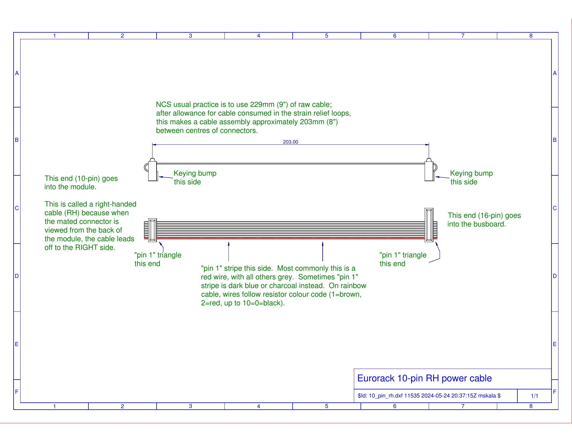
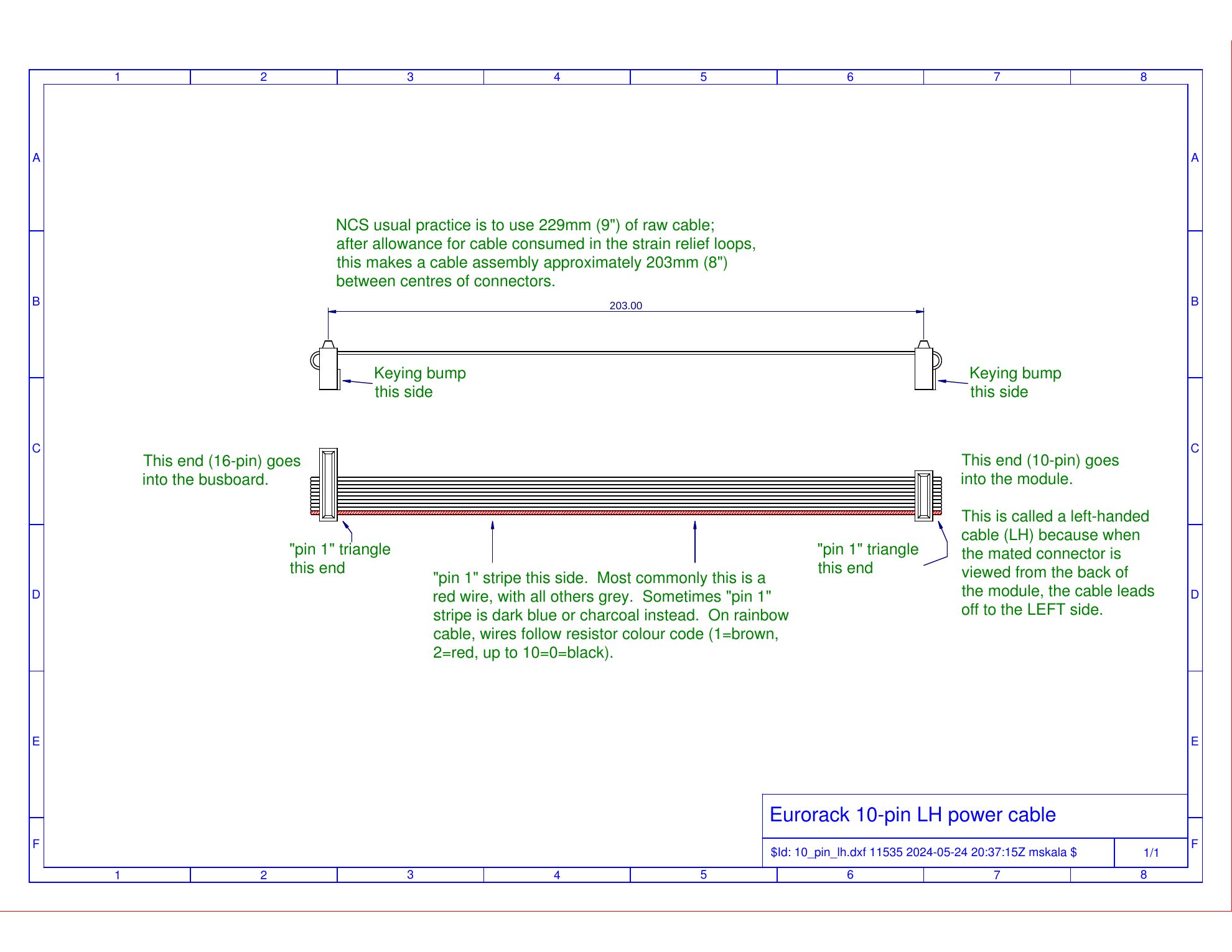
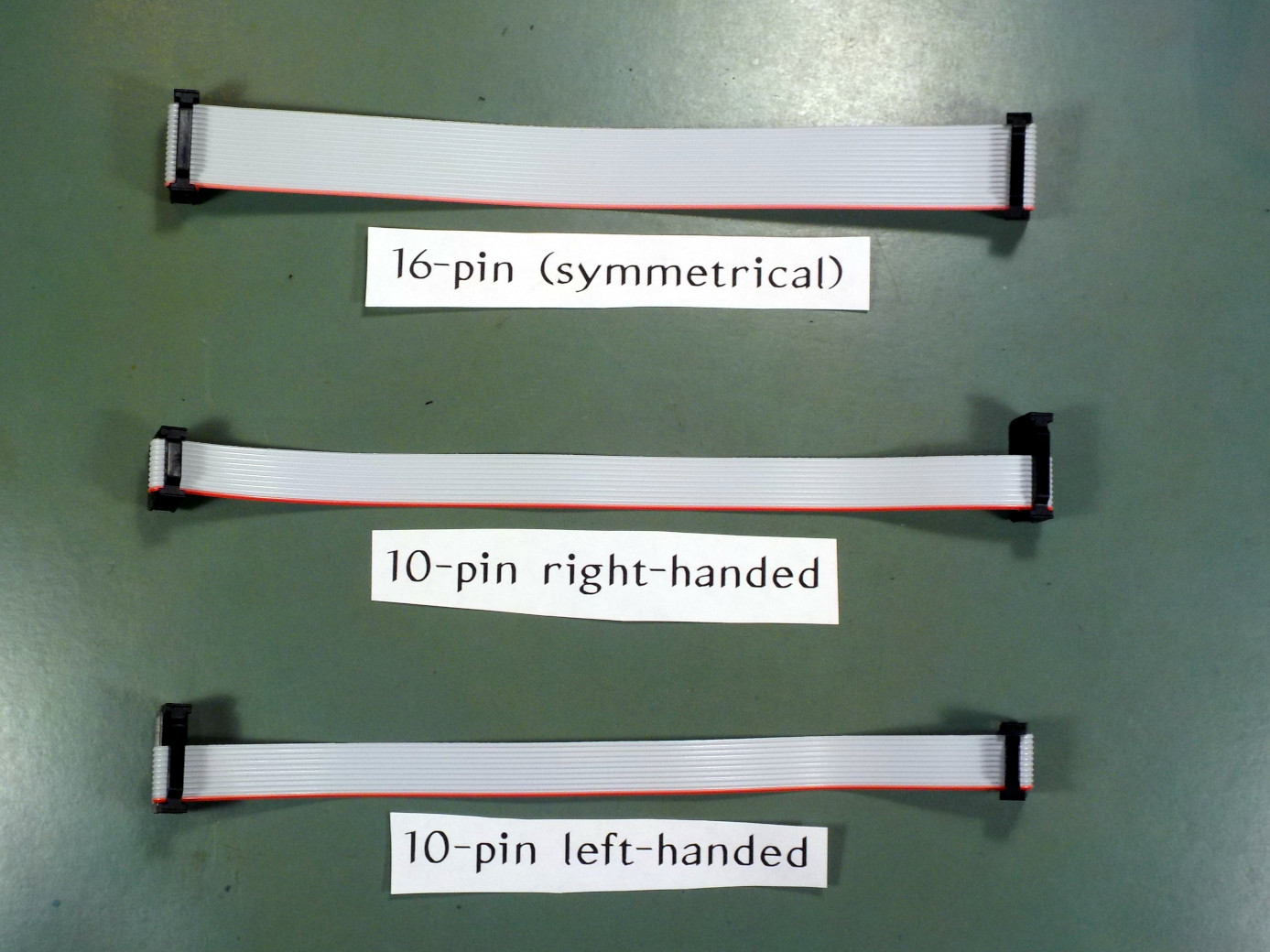
However, there's another decision to make that gets a lot less attention: you can insert the cable from the lefthand side or the righthand side. This is a separate decision from matching the pins. In a 16-pin cable, one end will usually have a "lefty" connector and the other will have a "righty," so the end-to-end symmetry cancels out the difference between the two, and there is only one kind of 16-pin cable. But the cable for a 10-pin module doesn't have end-to-end symmetry, and so there end up being two different kinds of 10-pin cables.
See the difference in these photos:
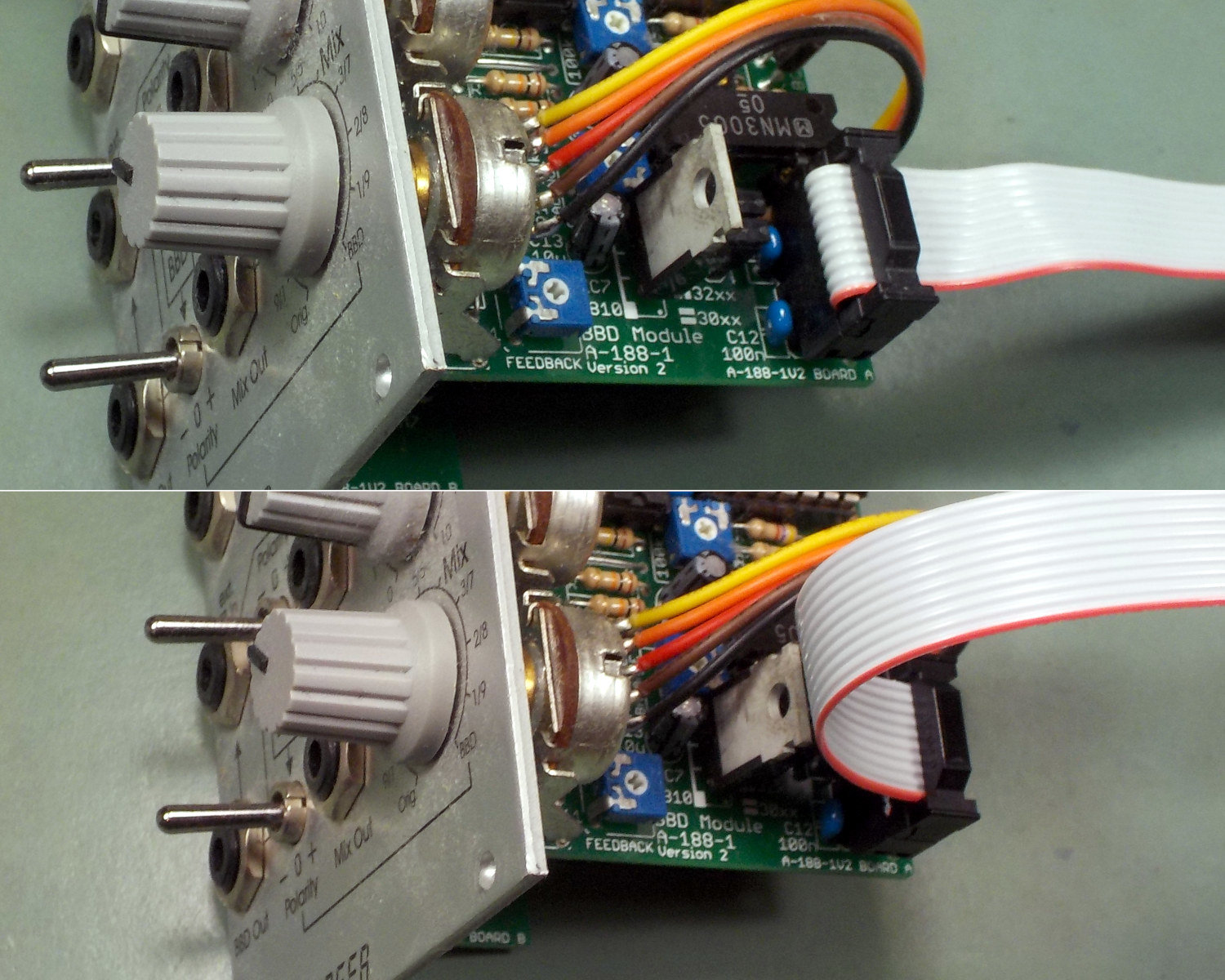
When a module has its power connection on a board that is parallel to the front panel, it may not matter much in which direction the cable leads out of the connector. But on a module like the one shown, where there's a circuit board at right angles to the panel and the power header is at right angles to that in turn, there can be an important difference. I call the cable assembly at the top "right-handed" because the cable, at the module end of the assembly, points to the right. The one at the bottom is "left-handed."
Quite often, perpendicular-board modules have their boards arranged such that the "component side" of the board is in the righthand direction from the point of view of someone looking at the front panel of the installed module. Then a righthanded cable assembly will have the cable pointing back, away from the front panel. That is usually what you want, so I think righthanded cables are more common in practice.
However, that's not guaranteed. My own MSK 011 Transistor Mixer, for instance, has components on both sides of the board in order to make best use of the available width. The power connection is such that it requires a lefthanded cable.
Many modules work fine with either kind of cable. Even when the opposite handedness of cable might be better, you can usually get away with using the wrong one, it's just less convenient; they both make the right electrical connections. And most manufacturers will supply the correct cable for each module when you buy the module, so if you keep modules with their original cables, you may not even notice that two kinds exist. But I'm a little surprised that I haven't seen much written online about these distinctions, because it does seem to be the kind of finicky detail that Eurorack users would find interesting. Two kinds of cable, which kind do you want?
There is actually even a further issue I haven't mentioned yet, which is that IDCs can be installed on either flat side (top or bottom) of the ribbon cable stock. Up to now I've been assuming both IDCs will be attached on the same side; but it's certainly possible to make a cable with them on opposite sides, and then the symmetry considerations become even more complicated, because the top/bottom question also interacts with the left/right question.
I have seen very few cables made that way and for the most part I think they don't need to be considered. But it's possible that in some special situation, if you had left/right direction constraints at both ends of the cable instead of just at the module, you might need a cable with the IDCs mounted on opposite sides.
Strain relief and cable length
The basic procedure for terminating ribbon cable with IDCs is to cut the cable, thread it through a slot in the IDC, and then squeeze it with a crimping tool. The connector has a built-in set of carefully spaced blades, and when it's squeezed, the blades cut through the insulation and make contact with each wire. They're not supposed to actually cut the wires: instead, the wires get squeezed into unsharpened slots in between the blades, being crimped in such a way that they make a good electrical contact. The sizes and arrangements of the different parts of the connector and bulk cable stock are carefully worked out so that this all works in a reasonably foolproof way.
Some variations and special effects are possible, such as the Eurorack thing of sliding a 10-pin cable over to one end of the slot in a 16-pin connector to connect only a subset of the pins; attaching connectors in the middle of the cable to create a bus with three or more positions (like the "flying busboard" used in cheap Eurorack power systems); or slitting and rearranging wires in the cable to change the pinout between connectors, as was done with some old hard drive cables.
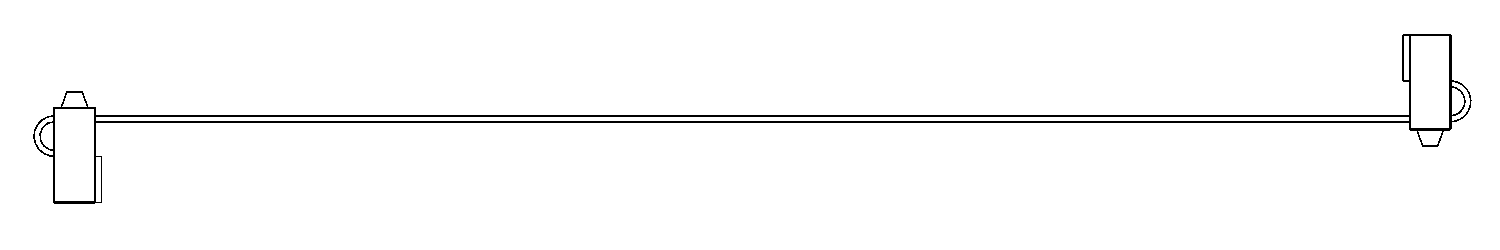
But another thing you'll see that makes some ribbon cable assemblies different from others, is the strain relief loop and clip.
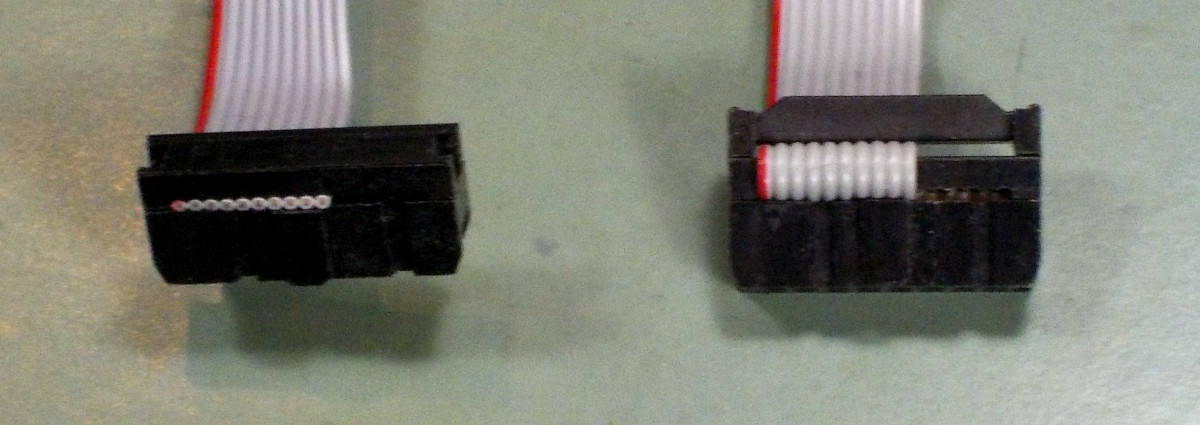
Suppose the cable goes straight into the IDC, as shown at left in the photo. Then if someone pulls on the cable while it's plugged in, the strain is applied directly to the wires where they go through the contact blades inside the connector. That could be an opportunity for damage.
In the cable assembly at right, the cable loops back over the top of the connector, and there's an additional clip on top holding it firmly in place. Pull on that one while it's plugged in, and the strain is applied to the clip rather than the blades - a place where strain is less likely to be damaging.
Using the strain relief clip isn't a no-brainer, because it makes the connector taller. In a tight location like a synthesizer skiff, those extra millimeters may make an important difference, and users may prefer to have lower-profile non-strain-relief connectors and just be a little more careful not to pull on them. I'm not sure which way is really better for Eurorack, and at various times in the past I have used both. However, in all my recent cable assemblies I've opted to use the strain relief clips, and in a quick informal survey of the cables I have on hand from other manufacturers, it looks like most other Eurorack companies, but not all, use strain relief clips by default.
It also is only reasonably possible to use strain reliefs on connectors at the end of the cable. Intermediate connectors on a cable with three or more pretty much have to be attached without strain relief, unless you're creating a very unusual assembly where the entire cable profile makes a 180° turn at the location of the intermediate connector.
If you're going to use strain relief clips, and associated loops of cable, when making a cable assembly, then you have to crimp each IDC on the opposite flat side of the cable from where it should finally end up, accounting for the 180° bend made in the cable when you apply the clip. There is also a certain amount of cable length (roughly half an inch at each connector) used up in the strain relief loop, so if you want the finished cable assembly to be a specific length, with strain relief loops on the connectors, then you must allow a little extra when measuring and cutting the bulk cable stock.
That brings up another interesting question: how long should a Eurorack power cable be?
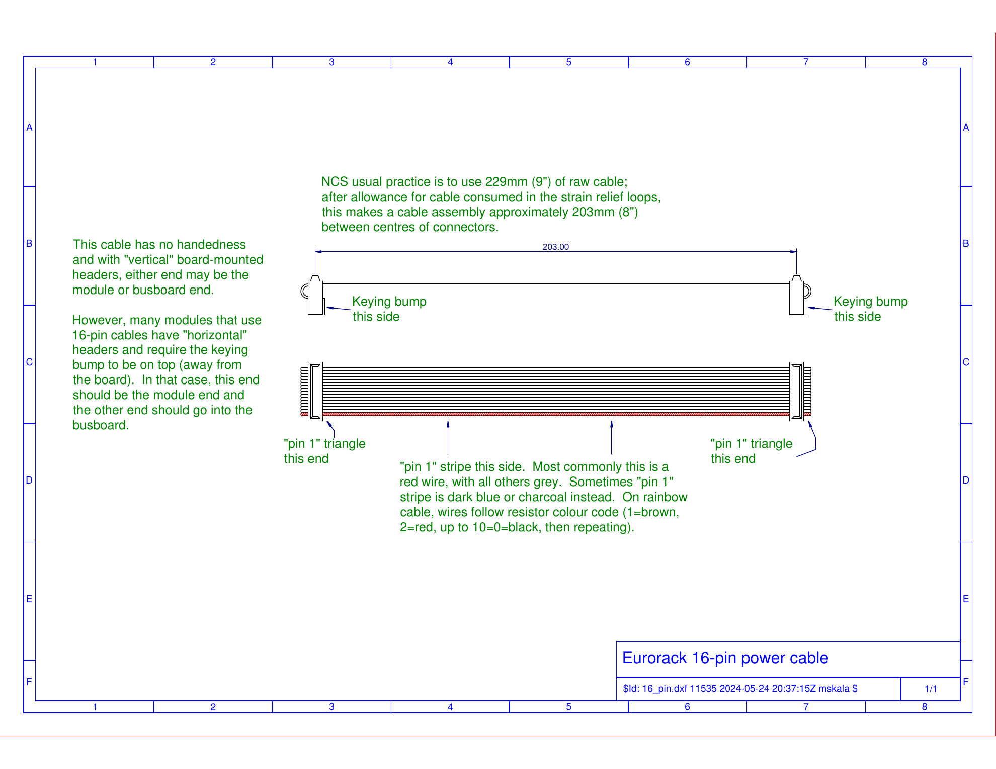
I don't know of any real standard. What I normally do is cut a 9-inch (229mm) piece of bulk cable stock for each cable assembly. When terminated with strain-relief IDCs, which consume about half an inch at each end, that results in a cable assembly measuring about 8 inches (203mm) from centre to centre of the connectors.
I think that's about the right length for a Eurorack cable. It seems to work well in my own rack, and my customers generally seem satisfied with it. Shorter, and in large racks the cable might not stretch from the module to the busboard. Longer, and it leads to a "How are you going to fit that in there?" situation stuffing the excess length into skiff-type enclosures where there is very little space to spare. But it's easy to imagine special situations where a significantly longer or shorter cable assembly might be desired.
Cut, crimp, test
After deciding which side to insert the cable stock into the IDC and whether you want the keying to be right or wrong, there's also the important step of actually squeezing the IDC to drive the connection blades through the insulation and crimp the wires.
Many hobbyists attempt to crimp IDCs in a benchtop vise instead of using a proper crimping tool. I've even heard of someone using channel-lock pliers because they didn't have a vise. The main problem with these makeshift methods is that it's hard to get the amount of pressure right: you are likely to either crush the plastic of the IDC body, or leave some of the wires not fully crimped. That makes the reliability of the finished cable assembly lower.
A secondary issue with using the wrong tools is that even if they work, they are more work. That is to say, it takes longer to set up an IDC in a vise and then turn the screw to crimp it, or edge along its length with channel-locks, so you spend more labour per cable. That's not such a problem if you're only making one cable, but more of a problem if you are making a batch of 20 cables, and a bigger problem still in a commercial context where you might be paying an employee to make the cables. For this reason, the professionals invest in specialized crimping tools for making IDC cables.
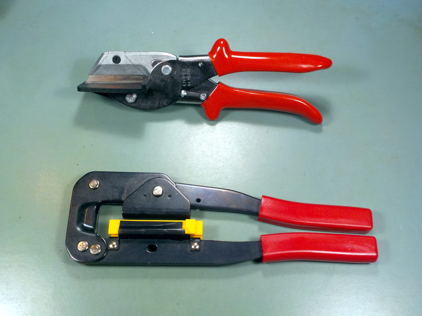
At bottom in the photo above is the basic Chinese hand crimping tool for ribbon cable IDCs. I have seen this same tool for sale under at least a dozen different brand names, all priced at about $40, and as far as I can tell they are all exactly the same. They're probably all made in the same factory. Anyway, this tool is not great - it takes some practice to get good results with it, it strains one's hands if used too long without a break, and the yellow crimping die tends to fall out unless you tape it (as I did, in the one shown in the photo). However, it is basically the only game in town unless you make so very many cables as to justify spending several hundred dollars on a more elaborate name-brand tool. And it is a significant improvement over trying to use a vise.
The tool at top in the photo is an anvil cutter. It's often overlooked, but important. Discussions of DIY ribbon cable construction usually go into detail on the crimping step, but before that you need to cut a piece of cable off the roll, and exactly how to do that is often taken for granted. Are you going to use scissors? You will dull them cutting wire, and the cut won't be clean anyway. Are you going to use diagonal cutters? Most of those make a curved cut, and aren't long enough to go across a 16-pin ribbon, so you end up having to take two squeezes at it and getting a non-straight cut end. The anvil cutter uses a straight blade and gives a very clean cut. The one shown in the photo is actually my second anvil cutter. I wasn't satisfied with the first one I bought (which used a built-in non-replaceable blade) and upgraded to the one shown, which takes a utility-knife blade that starts out sharper and can be replaced when it wears out.
Even if your cutting and crimping tools are good, but all the more so if they aren't, there is a risk that cable assemblies may turn out defective. If there's a small misalignment in the cable when it goes into the IDC, it's possible that the contact blades may cut where they're not supposed to and one blade may touch more than one wire - creating a short between them. Usually it'll be two wires that are next to each other in the cable, which in the case of Eurorack power means either that those two wires will be carrying the same voltage (in which case the short will go unnoticed; not much harm done), or it'll be a short between +12V or -12V and ground. Plug a cable like that into your busboard and, at best, the power supply will detect the overload and shut itself down. This kind of defect gets less common as you gain experience with making cables, but as with soldering mistakes, the error rate is never perfectly zero.
So it's advisable to test every cable after making it. My own practice is to test the freshly-made cables using my proprietary testing device (described in the earlier article at that link) before putting the cables on the shelf. Then when I'm doing quality control on a freshly-built module, I take an appropriate cable off the shelf for plugging in the module, and after that, that particular cable stays with that particular module until I sell it. Modules get another QC check before being packed up and going out the door, and in that check I use the same cable again. So in the case of a cable sold with a module, the cable gets tested at least three times before the customer gets it, and two of those tests are with the specific module in question, confirming that that cable works with that module.
Cwejman cables
For reasons that have never been made clear, the late Wowa Cwejman designed his famous modules with keyed headers on the back in the opposite of Eurorack pinout: pin 1 at the top, but the -12V supply still at the bottom. The result was that plugging in a standard Eurorack power cable would apply reverse power to the module. Fortunately, all or almost all of these expensive and now hard to replace modules included reverse-protection diodes, so they wouldn't be destroyed by such an error. But to get one to actually work, you needed a special power cable with the keying reversed.
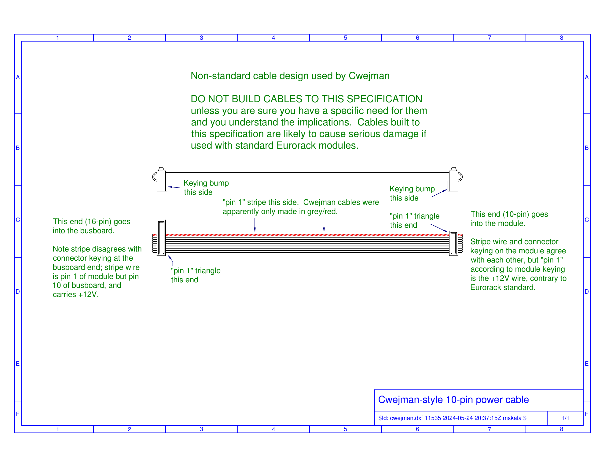
Note that at the 16-pin busboard end of the Cwejman 10-pin cable, the stripe is in the middle of the connector. Standard cables, in all versions, have the stripe at the end of each connector, never in the middle.
My understanding is that most Cwejman modules used 10-pin cables like the one shown above, and they were right-handed from the point of view of the module connector keying, also as shown above; but there were also some 16-pin Cwejman cables made. Those were much like the 10-pin version, with a backwards-keyed connection on the module (-12V at bottom on pins 15 and 16, gate signal at top on pins 1 and 2); cable stripe matching the keying at the module end; and cable stripe contrary to the connector keying at the busboard end.
I've heard this unusual keying described as just a matter of personal preference - could go either way, Doepfer happened to choose one way and Cwejman the other. I don't think we should make that excuse, though. There's a right way and a wrong way for cable keying to work, and the Cwejman cable assemblies are simply wrong. They connect pin 1 on one side to pin 10 on the other side and vice versa, with a marking on the cable as such that can only correctly match the connector at one end, not both. That is even before we get into practical questions like entering an existing market where there's an existing standard already, with cables that are easy to misuse in a destructive way. Even if Cwejman's own modules were all reverse-protected, the existence of these cables poses a threat to other modules that might be depending on the cable keying and stripe direction.
Whatever I think, these cables exist. It's worth knowing about them. And even if not deliberately made for use with Cwejman modules, enough people have made incorrectly-keyed cables simply by accident that we can't depend on cable keying and "shrouded" (properly speaking, keyed) headers to prevent power reversals.
◀ PREV Card payment update || Build your own commercial module part 5: pricing your module NEXT ▶
10-pin RH grey power cable
US$2.87 add-on item
Comments
The whole thing of there being multiple commercial module businesses, and end-users who were not electronics hobbyists repeatedly plugging and unplugging modules from multiple manufacturers in the same system, was not the original idea at all.
Now with that in mind, as soon as there are any significant number of unkeyed headers in the wild, or mis-keyed cables (like from Cwejman...), then you can't tell end users to depend on the keying anymore, because if the cable is plugged in backwards at the other end, or made incorrectly, zap. And that boat was out of the barn long before Doepfer reached the point of being forced to admit that Eurorack had become an ecosystem and wasn't just A-100 and a few little hangers-on anymore. Now we're all pretty solidly stuck with "you have to really do the work to figure it out" and "it's a good idea for modules to include reverse-protection circuits" regardless of connector keying.
That doesn't necessarily mean I would try to forbid keyed connectors, but I think it may be understandable that Doepfer does. With unkeyed connectors you always *can* plug them in correctly, but you have to pay attention. With keyed connectors in a system that may contain mis-keyed connectors, plugging them in correctly may be impossible, whether you know which way is right or not.
It's open for comments here:
https://docs.google.com/document/d/12nqRkrmzlgwcNGsrpQdlVzxgrLeheadf8qbS2G-UXMk/edit?usp=sharing
Cheers,
Advising against shrouded headers is like advising against buying mushrooms from the grocery store because they might be misidentified poisonous ones. Instead you should only get your mushrooms from the wild and ID them yourself!