Tickling twonies with triangle waves
2024-04-27 science! electronics MSK 013
There's been a plague of bad twonies in Toronto recently. These are counterfeit Canadian $2 coins. They've been called "camel toe twonies" because one of the most visible features of the bad ones is that the right front paw of the polar bear on the reverse is misshapen, vaguely resembling the toe of a literal camel and not any other meaning of that term.

The initials of the artist, "BT" for "Brent Townsend," are also missing on the counterfeits. A real twonie is shown for comparison below.

I recently received one of the bad coins in change from a cash transaction, and it's interesting to compare it with good ones. Just looking at the bad one by itself, I have to look closely to see anything wrong with it. But if I hold it and a good one in my hand and look at them both, it's obvious there's a difference. The most noticeable thing is actually that the bad one is shiny in a different way from the good ones.

The shininess of coins is difficult to photograph well or to describe precisely without technical terms, but the thing is that the bad one has more of a chatoyance or cartwheel effect to it. That is sort of visible in the photograph above (bad one is at upper right), and even good coins often have it to some degree, but it's clear when seeing the coins in real life that the bad one has an unusual amount of chatoyance. Also noticeable is that the yellowish centre of the coin has a more greenish hue on the real twonies, more reddish on the camel toe twonie.
Since I can't spend the bad coin, and I'm not sure where I received it, I figured before destroying it I'd take the opportunity to do some measurements on it. I have a rough idea of how vending machines and such use the "electromagnetic signature" of coins to distinguish good ones from bad ones, and different denominations from each other, so I thought it would be fun to try to reproduce that process on my electronics workbench.
As a warm-up, here are the weights of ten good twonies and the bad one.
| year | weight (g) |
|---|---|
| 1996 | 7.31 |
| 1996 | 7.31 |
| 1996 | 7.32 |
| 1996 | 7.32 |
| 2004 | 7.35 |
| 2007* | 7.08 |
| 2013 | 7.00 |
| 2015 | 6.93 |
| 2016 | 6.89 |
| 2016 | 6.90 |
| 2018 | 6.95 |
The Royal Canadian Mint changed the design of the twonie significantly in 2012. Pre-2012 twonies have an official standard weight of 7.30g, and post-2012 twonies 6.92g. There are also differences in thickness, and (importantly for the electromagnetic tests we'll be doing) alloy composition. The bad one purports to be from 2007. As the population in the table above implies, there are still a lot of twonies in circulation from 1996, when the $2 coin was first introduced, so I ended up with a lot of those when I went looking for a sample to compare against.
Overall, it looks like my weight measurements are pretty close to the official weights. My average reading for the pre-2012 good twonies is 7.322g, and for the post-2012 good twonies it is 6.934g. It's reasonable to expect circulated coins like these to vary a little in weight, as metal wears off (lowering the weight) and dirt accumulates (raising it).
At 7.08g, the bad one is in between the pre-2012 and post-2012 weights, far enough from either of them to be suspicious for the weight alone. The really interesting question, though, is how the coins respond to magnetic fields.
Any time an electric current flows, for instance through a wire, it creates a circular magnetic field around the direction of flow. Arrange the wire into a coil and the magnetic fields of the individual turns reinforce each other. The influence also works in the opposite direction: magnetic fields create electric currents. This interplay between currents and fields gives rise to the effect known as inductance.
In my article on why you need complex numbers, I talked about how an AC voltage applied to a capacitance results in current leading the voltage: the maximum forward current occurs as the voltage crosses zero, then decreases as the current increases. That comes about because of the energy stored in the capacitance in the form of an electric field; and the mathematical consequence is that the capacitance has something called reactance, which is like resistance but best measured using an imaginary number. An inductance similarly exhibits current phase-shifted relative to the voltage, but in the opposite direction. There is energy stored in the magnetic field, which must change whenever the current changes, so the current changes lag the voltage changes, as energy is transferred into and out of the magnetic field. Inductive reactance is, like capacitive reactance, best expressed using an imaginary number, but it's imaginary in the opposite direction.

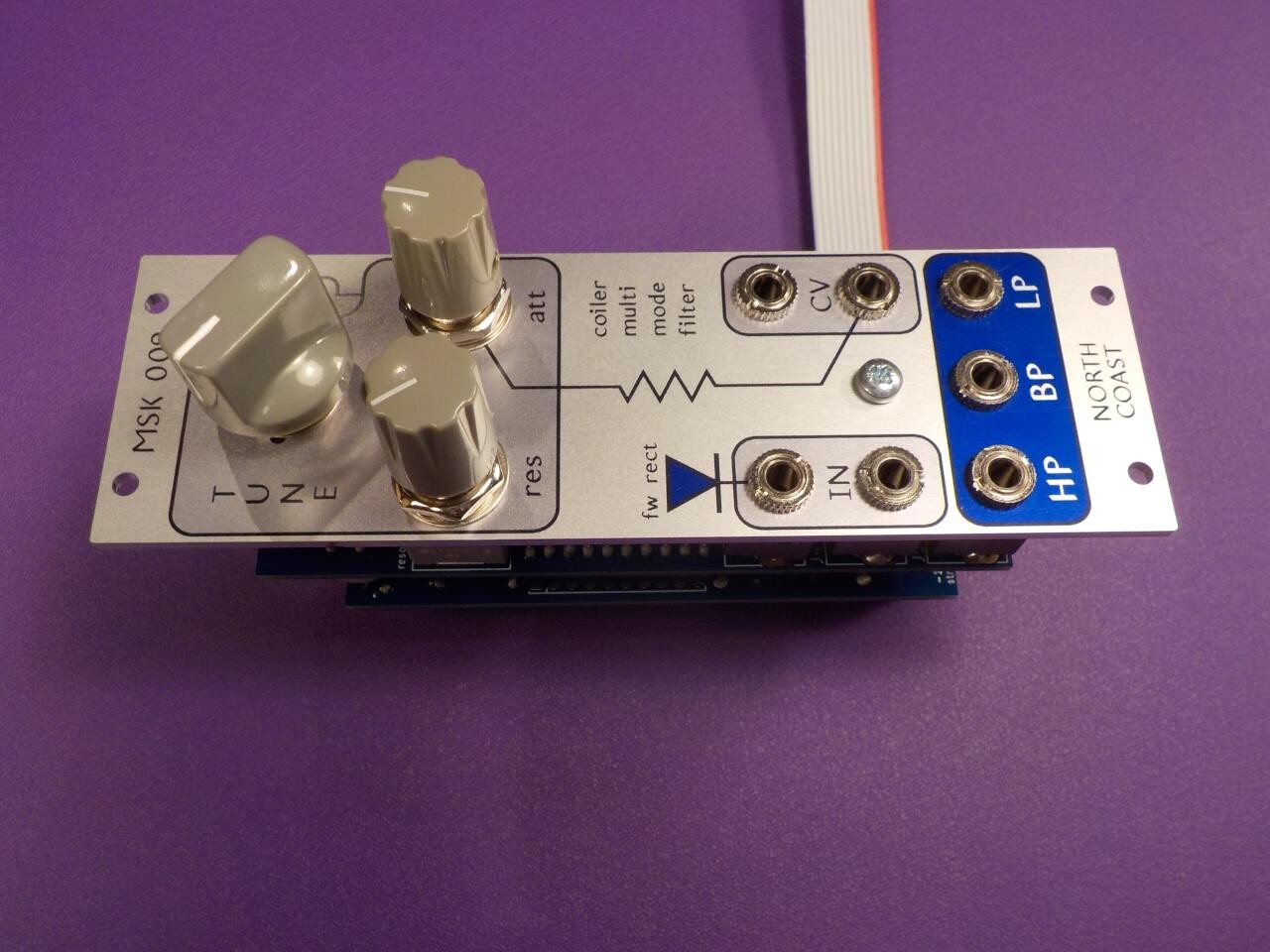
The North Coast Synthesis Ltd. MSK 009 Coiler VCF is an example of a synth module that uses inductance instead of the more common capacitance, in the integrators of an otherwise-straightforward state variable filter.
Real-life capacitors are different from theoretical capacitances partly because the electric field exists in a dielectric material which can only approach, without perfectly achieving, theoretical perfection. But in fact, we have access to inexpensive dielectric materials (polyester film is one) that come so close to the theoretical ideal we can usually pretend film capacitors are basically the same as ideal capacitances.
A similar approach to perfection is not seen in the magnetic materials used for building inductors at audio frequencies. In order to get a usefully high inductance value from a coil of wire, it's necessary to pass the magnetic field through some kind of material with a high permeability, meaning that it can hold a stronger magnetic field than would exist in just plain air or vacuum. And most of the available high-permeability materials are far from theoretically ideal. A real inductor (the component) will often behave not as a pure inductance (the mathematical abstraction) but as an inductance combined with a resistance, maybe a bit of capacitance thrown in as well, the whole thing changing properties at different frequencies and depending nonlinearly on power level, and so on.
Non-ideal behaviour of magnetic material is significant for ferrite beads, as described in my article on those. Ferrite beads are often shown using inductor symbols on a schematic, and assigned reference designators like L1, L2, the same as inductors; but as the frequency increases they tend to exhibit more resistive behaviour and less inductive behaviour than we'd otherwise expect. In their intended application of filtering radio-frequency interference, that's a good thing, because we want the interference to be simply dissipated (resistive behaviour) instead of getting into some kind of resonant peak (from an inductance).
The Coiler design is another place where I'm trying to make a virtue of the non-ideal behaviour of real inductors, and in fact it uses ferrite material too. Because the coils in the module are non-ideal, and they do somewhat unpredictable things with the signals, they change the sound of the filter into something unique that wouldn't be achievable in a filter that used only capacitors for integration.
Back on the subject of twonies, the important issue here is simply that the behaviour of an inductor depends a lot on what kind of material the magnetic field passes through. We should be able to distinguish materials by how they behave as inductor cores. If different coins are made of different metals, then we can hope that a coil will show different inductance and resistance - more generally, different complex impedance - as we put different coins inside the coil.
My plan, then, was to try to measure such differences. I'd build a coil, put different coins inside it, measure the impedance, and hope to get interesting results that could in particular distinguish the bad twonie from the good ones.
I'm not claiming to have made any very accurate measurements here. The equipment I'm using is what I had or could easily build, given the amount of time and money I was willing to spend on the project, and the fact that I wanted to involve my own synthesizer modules in order to have an excuse to advertise them. The point isn't to build a commercial-quality counterfeit detector; only to hope to see a difference between coins at all, and have some fun along the way.
I built a coil form out of Lego and wound about 200 feet of 30-gauge magnet wire around it. I'm not sure how many turns this was, but a few hundred, anyway. The coil form has a slot in it big enough to slide in a twonie, with some internal features arranged so that the coin will sit in a consistent position each time instead of moving around.

The idea is to measure the complex impedance of this coil, first with nothing inserted and then with each coin in my sample, including pre-2012 real twonies, post-2012 real twonies, and the counterfeit twonie. There are commercially available pieces of measuring equipment for this kind of task. They're called "impedance bridges," and they basically function like conventional ohmmeters but with a complex-number display showing the resistance and reactance in a single reading. I don't have such a device and wasn't about to rush out and buy one, so I ended up basically building my own.
Ideally, I would measure the magnitude of the current through the coil, and its phase relative to the applied voltage. I actually do have a "current probe" for my oscilloscope, which I used in my inrush current measurement project, but I'm not sure how far I trust it (in particular, with respect to phase shifts). I'd rather use the oscilloscope in the mode where it measures the magnitude of two AC voltages at once, and the phase diffrence between them. I use the phase-difference feature a lot in doing the precise adjustments on Leapfrog VCF builds.
So bearing in mind Ohm's Law (voltage and current proportional to each other), it seems I could pass a current through both the coil and a known resistance, and measure the voltages across the coil and across the resistance, to derive the current through the resistance (including its phase), which would be the same as the current through the coil because they're in series. A technical point makes it more complicated: my oscilloscope and signal generator both want to be grounded, so I can't measure two voltage drops independently, only voltage from two points to ground. I ended up creating (with alligator clips, patch cables, and so on) a circuit something like the one below.

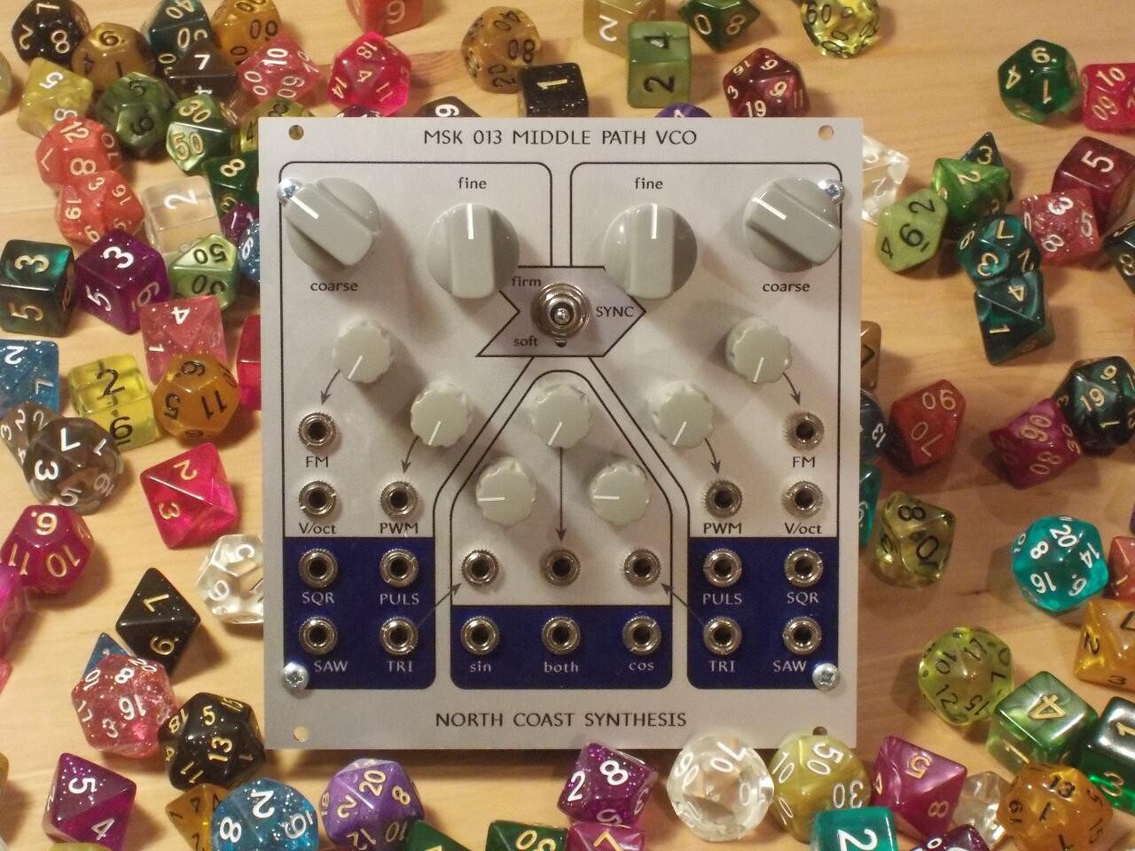
The known resistance of 1003.7Ω is simply a 1kΩ resistor whose value I measured as precisely as my ohmmeter would let me. The AC source is an MSK 013 Middle Path VCO with the frequency knobs turned all the way up. I experimented with a few different signal generators and decided to use the triangle output of the Middle Path instead of trying to shape it to a sine wave. I could've gotten a higher frequency of sine wave by using the shaper section, but when I tried that I found that (because of the uneven properties of the different transistors in the shaper) it created some lower-frequency modulation that made phase measurements harder.
The scope seemed to give me better, more consistent measurements of phase when I used the triangle wave to excite the circuit instead of putting it through even a single cycle of sine shaping. Using the triangle wave will likely create some inaccuracy in the absolute impedances I calculate, but since the questions I'm interested in are about relative differences between the coins, the answers I get to those questions should still be valid.
I tested the coil empty (with no coin inserted), then each of the coins in my sample (10 good ones and one bad), then repeated all those measurements a second time, to get some idea of how repeatable they might be. Here are the results: raw readings of RMS voltage at points 1 and 2, phase difference between them, and the resulting calculated impedances.
| year | ϕ (°) | V1 (V) | V2 (V) | Z1 (Ω) |
|---|---|---|---|---|
| EMPTY | 66.5 | 1.76 | 0.66 | 266.0+82.1j |
| 1996 | 65.0 | 1.76 | 0.68 | 271.0+88.6j |
| 1996 | 65.0 | 1.76 | 0.68 | 271.0+88.6j |
| 1996 | 65.0 | 1.76 | 0.68 | 271.0+88.6j |
| 1996 | 65.5 | 1.76 | 0.68 | 271.4+86.8j |
| 2004 | 65.5 | 1.76 | 0.68 | 271.4+86.8j |
| 2007* | 62.5 | 1.80 | 0.74 | 282.2+100.4j |
| 2014 | 66.0 | 1.76 | 0.70 | 277.7+86.1j |
| 2015 | 66.0 | 1.76 | 0.70 | 277.7+86.1j |
| 2016 | 66.0 | 1.76 | 0.70 | 277.7+86.1j |
| 2016 | 65.5 | 1.76 | 0.70 | 277.4+88.0j |
| 2018 | 66.0 | 1.76 | 0.70 | 277.7+86.1j |
| EMPTY | 66.5 | 1.76 | 0.66 | 266.0+82.1j |
| 1996 | 65.5 | 1.76 | 0.68 | 271.4+86.8j |
| 1996 | 65.0 | 1.76 | 0.68 | 271.0+88.6j |
| 1996 | 65.5 | 1.76 | 0.68 | 271.4+86.8j |
| 1996 | 65.5 | 1.76 | 0.68 | 271.4+86.8j |
| 2004 | 65.5 | 1.76 | 0.68 | 271.4+86.8j |
| 2007* | 63.0 | 1.76 | 0.74 | 287.4+99.5j |
| 2014 | 66.0 | 1.76 | 0.70 | 277.7+86.1j |
| 2015 | 66.0 | 1.76 | 0.70 | 277.7+86.1j |
| 2016 | 66.0 | 1.76 | 0.70 | 277.7+86.1j |
| 2016 | 66.0 | 1.76 | 0.70 | 277.7+86.1j |
| 2018 | 66.0 | 1.76 | 0.70 | 277.7+86.1j |
One of the things visible from these readings is that they're mostly the same. That is to say, there's a component of 266.0Ω+82.1jΩ, corresponding to the impedance of the empty coil, and that is most of the impedance observed; but then both the real and imaginary parts increase a little whenever we insert a coin. The coin (made partly of magnetic metal, nickel or steel in the outer ring of real twonies) increases the inductance because of its permeability, but it also increases the resistance a little. We can think of the coin as being like a shorted single-turn secondary coil in the transformer created by inserting it in the coil form. Some of the current from the primary (main coil winding) is induced into the coin and then dissipated because the coin's metal is not a perfect conductor. But meanwhile, most of the impedance is the basically constant contribution of the coil itself, independent of the effect of the coin - bearing in mind that the reading for the empty coil was exactly the same the two times I measured it.
Then it's possible to draw a new diagram representing the effects of the coil and the coin separately.

The empty coil is modelled by a 266.0Ω resistance in series with a 1.25mH inductance. That latter value is calculated by solving the inductive reactance formula, XL = 2πfL, with the measured inductive reactance of 82.1Ω for the empty coil and the system frequency of 10.49kHz. (As mentioned, I am doing this calculation on the assumption of sine wave excitation even though that's not actually true.)
Subtracting out the empty-coil contribution gives a set of calculated impedances that represent just the effect of the coin. Do note the significance of these figures: I am not saying that the coin has an impedance of so many ohms, in the sense of being able to hook wires up to the coin and have it drop voltage in proportion to current accordingly. Rather I am saying that these numbers are the size of the difference in impedance imposed on the coil by virtue of inserting the coin in the coil under my test conditions. The real point is not the values themselves, but the fact that they are different for different kinds of coins.
| year | Z2 (Ω) |
|---|---|
| EMPTY | 0.0+0.0j |
| 1996 | 5.0+6.5j |
| 1996 | 5.0+6.5j |
| 1996 | 5.0+6.5j |
| 1996 | 5.4+4.7j |
| 2004 | 5.4+4.7j |
| 2007* | 16.2+18.3j |
| 2014 | 11.7+4.1j |
| 2015 | 11.7+4.1j |
| 2016 | 11.7+4.1j |
| 2016 | 11.4+5.9j |
| 2018 | 11.7+4.1j |
| EMPTY | 0.0+0.0j |
| 1996 | 5.4+4.7j |
| 1996 | 5.0+6.5j |
| 1996 | 5.4+4.7j |
| 1996 | 5.4+4.7j |
| 2004 | 5.4+4.7j |
| 2007* | 21.4+17.4j |
| 2014 | 11.7+4.1j |
| 2015 | 11.7+4.1j |
| 2016 | 11.7+4.1j |
| 2016 | 11.7+4.1j |
| 2018 | 11.7+4.1j |
I plotted the "coin contribution" values on a Smith chart, scaled to put 10Ω at the centre of the chart. See my earlier article on Smith charts for more information about this kind of plot, as well as downloadable PDF Smith chart graph paper.
The fact that there are many duplicate measurements in the data set is a little unfortunate, but that's the consequence of the low resolution of my oscilloscope. I was only able to reliably measure phases down to half a degree and voltages to 0.02V or 0.04V, and with many nearly-identical coins, that resulted in coinciding measurements. In order to represent those on the chart, I scaled the dot sizes by the square root of the number of coinciding points. That makes the area of each dot proportional to how many measurements were plotted there.

And that chart is really the punchline of the experiment. To the question, can I tell the difference between real and fake twonies from their electromagnetic signatures?, it seems the answer is definitely yes. The measurements on the fake one end up in a distinctly different cluster from all the others, and the difference is much bigger than the variation within each cluster.
It's interesting, though, that there is also a similar-sized difference between the pre-2012 and post-2012 genuine twonies. Coin discriminators that used this kind of measurement presumably required some significant adjustments in 2012, in order to be able to accept the new coins.
Thinking about the nature of the changes that the Mint made in 2012, I think the most relevant one was switching from 99% pure nickel for the outer ring of the bimetallic coin, to nickel-plated steel. Both metals are magnetic, but (to a varying degree depending on what kind of steel) steel is likely to have greater resistivity. Looking at the plot and the direction of the grid lines, it's evident that the inductive part didn't change a lot in 2012 but the resistive part increased.
The fake one is clearly made of significantly different material from either population of real ones. It contributes a fair bit more of both inductance and resistance to the coil's impedance. I don't know what the fake one is made of, but it's reasonable to guess that it would be something cheap while still looking enough like a real twonie to "pass." Perhaps its outer ring is also steel and nickel like a real one, but with a different (more magnetic and resistive) grade of steel and more steel overall, less nickel. The colour difference makes me think the inner, yellow part is probably also a different alloy, but it's reasonable to guess that it's still some kind of copper alloy, and I think that is probably less significant to the impedance effect.
If I were going to push this kind of experiment further, I think I'd focus on the geometry of the coil, which is probably not ideal. I built it the way that was convenient, but that ended up not really putting a large fraction of the magnetic flux through the coin, so that the coin's contribution ended up being small in comparison to the overall impedance. With a different physical design for the coil I could probably make the coin have a larger proportional effect on the overall impedance. Another thing I might do would be to explore other excitation frequencies. I used 10.49kHz because it was convenient to generate using the Middle Path, which I wanted to use; but I think it's customary to run in the ultrasonic range for this kind of measurement, and doing that would allow inductive reactance to be a bigger component of the overall impedance.
The coin discriminators in vending machines really do operate on a principle very much like what I'm doing here. Metal detectors, used by hobbyists to search for lost coins and other valuables, are also similar: a big coil, an ultrasonic signal source, and circuitry that attempts to characterize the way the coil's impedance changes when it gets near a piece of metal. Often in a metal detector, the coil is actually part of the tuning circuit for the oscillator, so the frequency changes when the impedance changes and then there's an audio beat frequency generated by the difference between that and a non-changing oscillator frequency.
A modular synthesizer may not be the ideal way to identify real and fake coins, but every so often on the synthesizer fora, someone proposes the idea of renting out modular systems. Maybe we could pay for that with a module that takes coins.
◀ PREV Outrunning the Noise Bear || Building a PIC24F phase meter NEXT ▶
You mentioned the 009 coiler filter, I already own this filter and came to your site today to have a look at the 009's details as I am trying to decide if I want the kit or ready made version this time around and saw this post. Anyway I am huge fan of the 009 filter because of its unique tone and presence in the mix.