Building a PIC24F phase meter
2024-05-22 electronics stripboard MSK 007 MSK 014
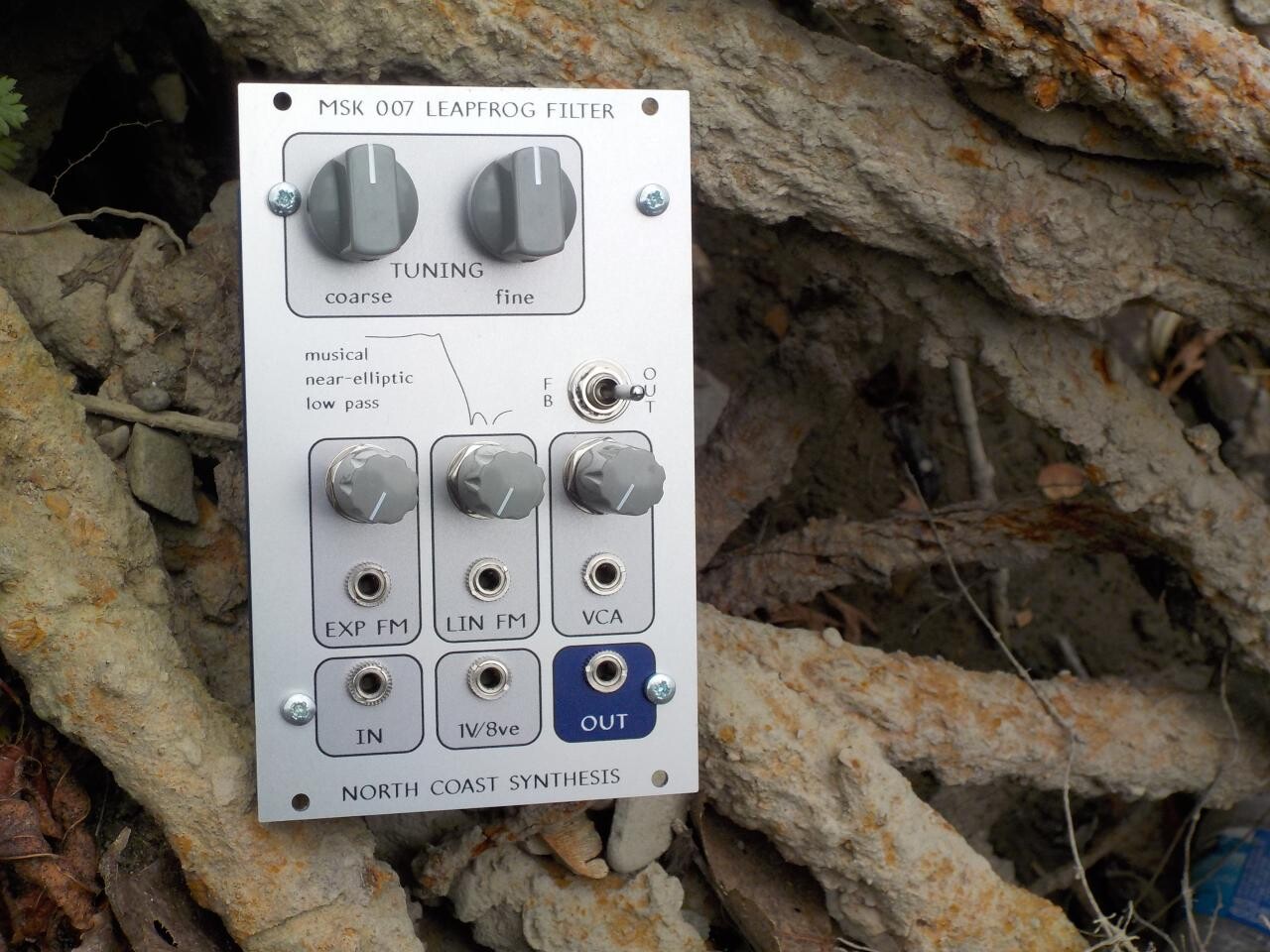
Adjusting an MSK 007 Leapfrog VCF to its best possible operation involves a tricky process of feeding in a 740Hz sine wave and measuring phase differences between different test points. I also had reason to measure phase differences in my recent experiments on recognizing fake coins. Although my oscilloscope has a mode for measuring phase differences that works well enough, it can be annoying to use, and I thought it'd be a fun project to build a better tool.
Anybody who builds electronics will gradually acquire a stock of "junk box" parts - leftovers from earlier projects, components pulled out of scrap equipment because they looked like they might be useful, stuff friends and relatives have given you because they know you like that sort of thing, and so on. Among the items in my junk box are a couple of rails of Microchip PIC24FJ32GB002 microcontrollers. These are close, but not identical, to the ones in the MSK 014 Gracious Host. They differ by having only 32K of programmable ROM.
The story is that when I was developing the Gracious Host, it was during the worst of the pandemic years and I was concerned I might not be able to actually get the PIC24FJ64GB002 chips I wanted to use. I bought some 32K chips because Mouser had those listed as "in stock," when the bigger ones weren't. It looked like microcontrollers in general would be very difficult to source for a long time, and I thought if worst came to worst, I could probably substitute in the smaller chips with only minimal changes to my Gracious Host hardware and firmware designs, instead of having to scrap all the work I'd already done. Better a bird in the hand, and so on.
As things turned out, I was able to source 64K chips for the Gracious Host a short time after that, and despite supposedly being "in stock," nearly all of the 32K chips ended up delayed to more than a year after I ordered them. So they arrived too late to use, and were the wrong ROM size anyway, and they've been on my shelf ever since. Even in the 32K version this is quite a powerful and expensive microcontroller, so I probably wouldn't use these chips in a product design unless it was a big, complicated product that really needed the features and could sell at a relatively high price - the Gracious Host itself is pushing the margins for being a big enough item to justify such a chip. But given that I have these 32K chips without another use for them, and they're already paid for, it makes sense to use one in my one-off project.
The phase meter
My idea was to build a device with two probes like a voltmeter's probes, and a display that would show the phase difference between the signals detected by the probes. There'd be a four-digit LED display showing the phase to a precision of 0.1 degree. It would also need some kind of connection for 0V reference as well as the probes, and ideally, it could could have a 740Hz sine wave output on a standard jack socket ready to be connected with a Eurorack patch cable, while taking its power from a Eurorack-style pin header and then having another such header for daisy-chaining the module under test.
Then I would have, all in one package, basically everything needed to do the phase-differencing adjustment on a Leapfrog VCF, instead of having to mess around with running a cable to my synthesizer rack for the sine wave, hook up the oscilloscope probes to measure phase difference, and try to read the randomly-changing oscilloscope display. I could just plug the module in, probe it, and read the phase differences on the display.
I was hoping to use as many components I already had as possible, to keep costs down. In addition to the microcontroller, I had some yellow 7-segment LED displays (missing decimal points, but that's one reason they were in my junk box), a bunch of old non-RoHS hookup wire that I'm trying to use up, a couple pieces of stripboard, ZXTP2012A transistors that I bought to evaluate and then rejected as replacements for the Leapfrog's PN200A transistors when those were discontinued, and so on. As well as "junk box" parts I was able to pull some of the needed components from my regular manufacturing stock that I use for making my module products; for bookkeeping reasons I'd have to "charge myself" for those (actually just moving money between one internal account and another), but at least they'd be parts purchased in large enough quantity that the price would be fairly low.
Here's a schematic of the design I came up with. Click for PDF.
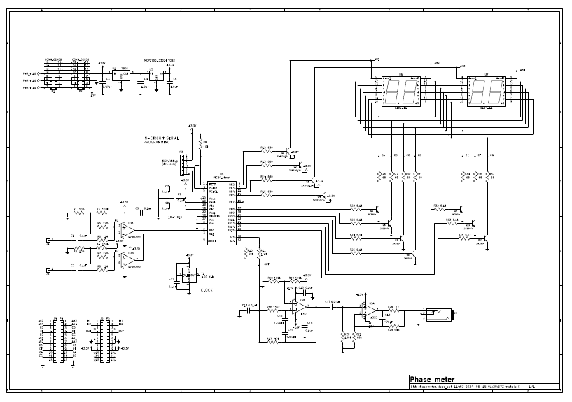
Do remember that this is specifically a design intended to use parts I already had, not necessarily how I would design something if I were building many copies, buying all the parts, and choosing the best parts on that basis. You can see things like how I used two 1200pF capacitors in series to make 600pF (C13 and C14) because I needed a value of about 600pF, I had lots of 1200pF capacitors, and didn't want to buy capacitors just for this project.
As I've written before, "having a lot of parts" to save money is useful when you're able to design your project around the parts you have. That's what I was doing here, and it was as much to save shopping time as to save money. It doesn't work so well to try to build a ready-made design and depend on "having a lot of parts" to save money on the ready-made design - because the parts you have a lot of, will either be wrong, or will be so small and cheap they don't really make much difference to the overall cost.
Probe inputs
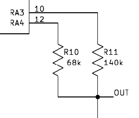
The microcontroller chip basically only accepts inputs in the range 0V to 3.3V. It has some pins that are supposed to be "5V tolerant," but the range of voltages I intend to probe with this phase meter is a fair bit wider, so some kind of protection is definitely needed. Also, I'd like to be able to catch the zero crossings of the input waveforms, and deal with "zero" crossings when the waveforms actually have some DC offset so that "zero" isn't really zero volts. That adds up to a requirement for AC coupling. Here's the input circuit I came up with.
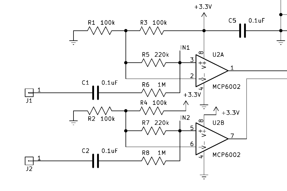
Each probe signal goes through a 0.1uF capacitor to eliminate DC. Then I'm using the two halves of an MCP6002 op amp - one of the few components I bought specifically for this project - as comparators to convert the signal into a digital form. The reason for using this particular op amp chip instead of one of the ones I already had on my shelf, was that it can run from the same +3.3V single-sided power supply as the microcontroller, and it has rail-to-rail output. So the op amp output is at the logic levels of 0V and +3.3V, perfect for reading with microcontroller GPIO pins. Many other op amps require a higher power voltage, and then cannot drive their outputs over the full range of the power supply.
In order to respect the op amp's input voltage limits, I'm using a resistive divider to scale down the input to about 21% of its original voltage, and centre it on half the power supply, namely +1.65V. This will allow it to work on an input of up to about 15V peak to peak, which is plenty for the application I have in mind. The input impedance, controlling how much this circuit loads down whatever it's probing, ends up being about 1.3MΩ, which is enough that it won't disturb a Leapfrog's test points, in particular.
LED drivers
The LEDs I'm using for the display are in common anode packages, because that's what I had in my junk box. Each digit has a single anode (positive to light up) connection shared by all the seven segments in that digit, and then the segments have individual cathodes (negative to light up). This configuration pretty much forces them to be driven by the matrix multiplexing scheme described in my digital LED driver article. Because the total amount of current, on the anodes in particular, is significant in comparison to the microcontroller's output capabilities, I ended up also adding transistor switches.
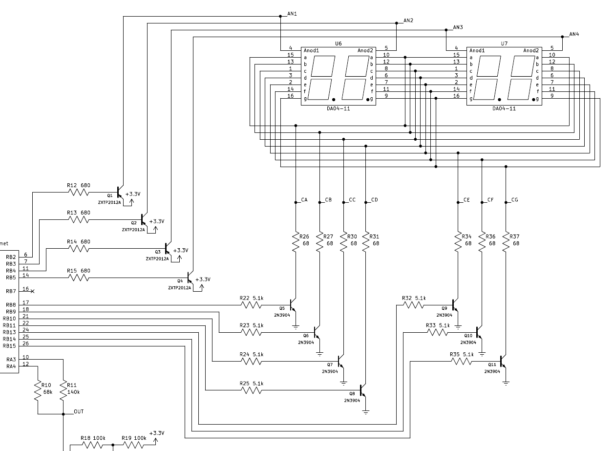
Each of the four per-digit anodes is assigned to one output pin on the microcontroller. Then all the "a" segment cathodes are connected together and assigned to one pin, all the "b" segment cathodes are connected together and assigned to another pin, and so on. Software on the microcontroller will pull down one of the anode-related pins at a time, turning on the associated transistor and bringing that digit's anode high. Meanwhile, it pulls up all the appropriate per-segment pins for the segments of that digit that should light up. For instance, to display the digit "8," it would raise all the per-segment pins. The corresponding transistors turn on, and the segments light up, but only in the digit that was selected.
The firmware rotates among the four digits at a rate of about 784Hz (for the complete cycle), so the switching between digits isn't visible, but if you recorded it on a high frame rate video camera you'd be able to discern that it is really only lighting up one digit at a time. Partly for that reason it's necessary to turn them on pretty hard, with nominally 20mA of current per segment, to get enough overall brightness. In the worst case the anode transistor is switching 140mA, which is more than the microcontroller can supply by itself.
This circuit also illustrates what you'll find is a common theme in microcontroller circuits: an important part of the work is actually done by software running on the microcontroller. The circuit itself is relatively simple and doesn't work all by itself.
Analog output
Here's the digital to analog converter for the sine wave output.
Wait, what?
As I said, in microcontroller circuits a big part of the idea is to make the computer do the work. I want to get an analog output from the microcontroller; but the microcontroller's output pins are digital-only, always producing 0V or +3.3V (or sometimes +5V if used in open-drain mode with an external pull-up, but that's beyond the scope). So to produce a voltage in between 0V and +3.3V, I will have the microcontroller switch rapidly between 0V and +3.3V in such a way that on average the desired voltage is whatever I want.
That technique, if using a regular pulse pattern and only changing the width of the pulses to make the voltage mostly high or mostly low, is called pulse width modulation (PWM). In this case I'm going a little further, to create a delta-sigma DAC, as discussed in my article on those. I'm also using two output pins on the microcontroller, with different resistors on them, to allow for a little extra resolution.
In operation what happens is that instead of producing a sine wave output directly, the microcontroller is going to produce two pseudorandom digital signals, such that when they're run through the voltage divider above and then averaged over time, the average voltage will be the desired sine wave. The switching rate is roughly 1MHz, so this can be thought of as a 2-bit DAC with 1MHz sample rate, trying to emulate a lower sample rate and greater bit depth. Sample rate is not tightly controlled because the firmware is written to just make the CPU do sine wave work as fast as possible whenever it's not busy with anything else. Because it's not tightly controlled and for other theoretical reasons, using a pseudorandom sequence is preferable to a more systematic switching pattern. The result is a sine wave with a lot of wideband noise in it, most of which is ultrasonic, and then I use a couple of LF353 units to filter out the noise and amplify what's left as a reasonably clean output signal at a voltage suitable for my purposes.
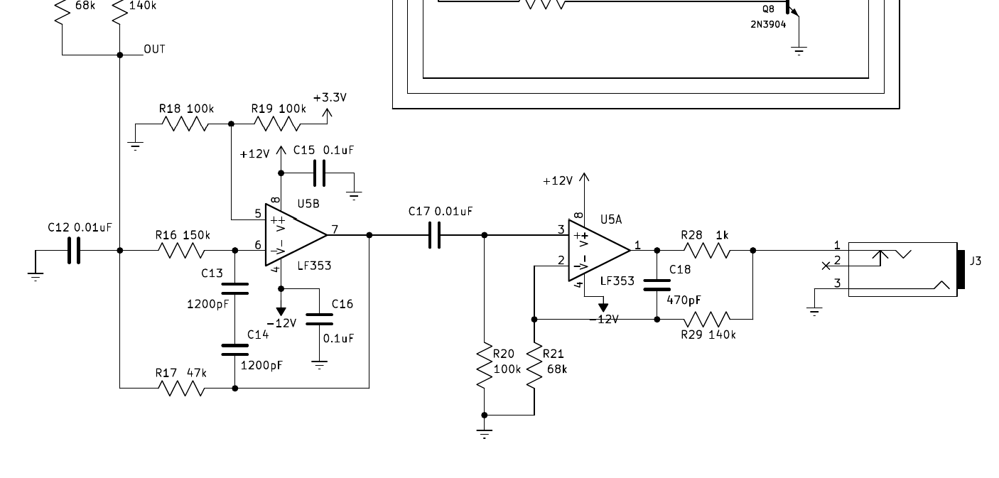
The result is certainly not perfect. There's some low-frequency noise that still makes it through the filter and is audible if I listen to the sine wave. I think the filter design (a multiple feedback low-pass filter sketched out with help from the Okawa Electric Design online calculator) is not optimal for the application; I might've done better to use a bandpass filter and higher Q. But the output frequency is accurate and stable, at least, it's reasonably free of harmonic distortion, and it seems to work well for the intended application of being an input to a Leapfrog during adjustment. Also, it was a chance to try out some ideas I had regarding this kind of homemade delta-sigma DAC, which I hope to use in other projects in the future.
Firmware
A lot of the work on this project actually went into the firmware, which I wrote in assembly language. I'm not going to post much detail on the firmware here, not least because I'm still modifying it; but you can get some idea of the kind of thing that goes into such a project by reading the Programmer's Manual for the Gracious Host, which uses a very similar microcontroller chip.
The phase meter firmware basically has three things to do:
- Detect edges on the input pins connected to the comparators and then to the probes, and from the timing of those edges, figure out how many degrees phase shift exist between the signals it's measuring.
- Drive the LED transistors to display the result of the phase calculation, including the logic of multiplexing digits so that they all appear to be lighted at once, as appropriate.
- Generate the pseudorandom sequences that will average out to a nice sine wave after they go through the output filter.
PIC24F microcontrollers are replete with special-purpose hardware and bonus features. My first thought on how to measure the timings of the input signals was to set up a hardware timer to count clock cycles (16MHz clock, 62.5ns cycle time, which is pretty good accuracy for measuring a signal at less than a kHz) and then use a hardware feature called "Change Notification" to ask for an interrupt on each edge. When there was an edge, the microcontroller would automatically jump to a subroutine that could take note of the time shown by the timer. Then foreground (non-interrupt) code could keep an eye on those recorded time values and use them to calculate the phase.
I had to learn how to activate "Change Notification," because I never used it in the Gracious Host code, and I found that it's really quite difficult and annoying to use. Among other things, there is only one Change Notification interrupt vector, and it triggers any time any input changes in either direction. So I couldn't just set up a routine to run on rising edges of input 1, say; instead I would have to run the interrupt on every edge of every input, keep a record of the previous state of all the inputs, check against that to figure out what input had changed and in what direction, and so on. All this made it hard to maintain accurate timing. I had expected, and found myself wishing, that turning on Change Notification would just make an input pin into an external interrupt request line, such as other computers have, but no, the PIC24F had to have this complicated and inappropriate feature instead.
Then while looking for something else in the manual, I saw a reference to "external interrupts"... and on further research I discovered that the PIC24F actually does have those too, they just don't have a chapter of their own in the manual as other features do. They're just sort of mentioned in passing in several places where it describes other features. So I went through the manual again, figured out how to use external interrupts instead of Change Notification, rewrote my code accordingly, and that was an improvement.
But even proper external interrupts weren't perfect, in particular because it could only handle one at a time. I could set priority between them and even allow one interrupt service routine to interrupt the other, but it remained that if both inputs had rising edges at once (that is, zero phase) the firmware would have trouble recording both time stamps at once and would end up with a spurious reading. I really wanted to take the CPU out of the loop of recording times.
The PIC24F actually has a special hardware feature for solving more or less exactly that problem. It's called Input Capture. Block diagram from the PIC24F Family Reference Manual.
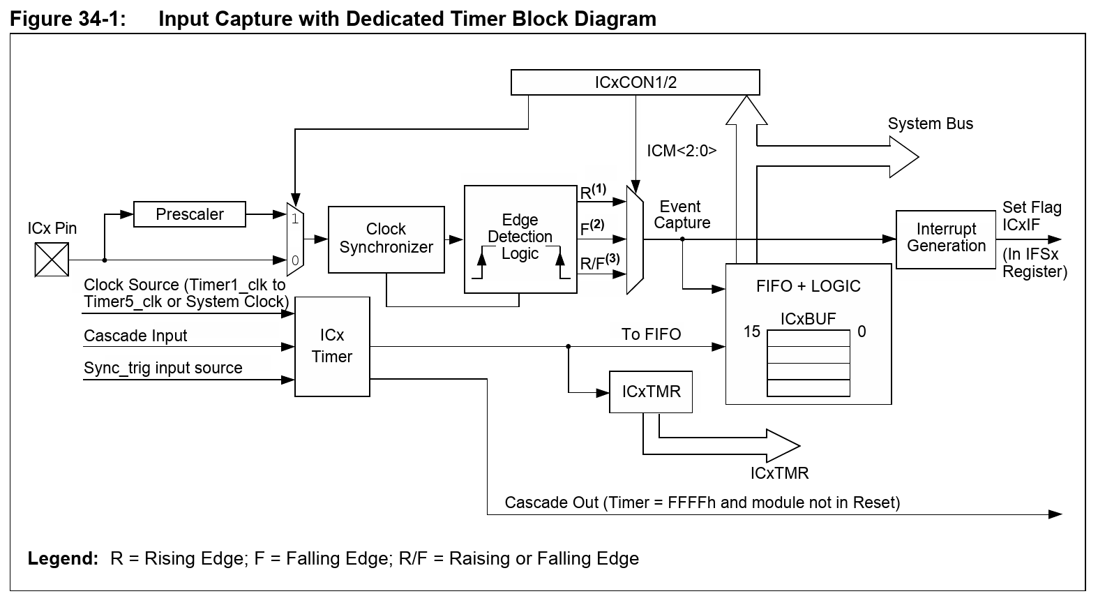
The idea here is that, when so configured, the input capture hardware will all by itself record the timestamps of edges on the input pins, and put them in a FIFO buffer. It can optionally also generate an interrupt on each edge, or perhaps once every so many edges (configurable), and then it doesn't matter whether the CPU serves the interrupt immediately because it can just pick up the timestamps from the buffer whenever its convenient.
But of course, that's another complicated hardware feature I hadn't used before, and the documentation for it is unclear, and it doesn't necessarily work exactly as the documentation says, and so on. Getting input capture to work properly took me a few extra days. But once I got it running, it gave much better results than the "external interrupt" and "Change Notification" methods I'd previously tried.
There were other challenges along the way that I probably don't need to describe in detail. Given the more or less accurate edge timings, I ended up having to implement 32÷32-bit long division to figure out the phase reading. One of my biggest annoyances with using my oscilloscope to measure phase is that noise usually makes the reading from a single cycle of input uncertain by about two or three degrees; to get a more accurate reading it's necessary to average several consecutive measurements, and I don't like trying to do that in my head. I added logic to the phase meter firmware to make it do an exponential moving average automatically. Then there were several iterations needed to get the sine-wave delta-sigma stuff working the way I wanted it, although that part was actually easier than I had feared.
At this point I'm starting to think I'd like to measure frequency too, which will require further revision of the firmware and maybe adding some pushbuttons for selecting different modes. I still have one unused I/O pin on the microcontroller, so my thought is that by adding buttons in series with diodes from each LED anode line to that pin, and a pulldown resistor, I can make the firmware scan the state of up to four buttons while it's doing the existing LED scan. The sampled sine wave table currently takes up almost all the ROM on the microcontroller, but I still have a couple of kilobytes remaining, which is probably enough to add a frequency counter even if I don't end up shrinking the sine table.
Building and using it
I built the circuit up on a stack of two stripboard pieces, with the microcontroller, LED driver transistors, and the input comparators on the bottom, and the LEDs themselves, output filter, and voltage regulators on the top. Except for the need to put the LEDs on top to make them visible, the division was basically between parts of the circuit that would use +3.3V power only, and parts that would handle Eurorack +-12V supplies.
Apart from the MCP6002 chip, the only parts I had to buy externally for this project were some banana jacks and a set of test probes, totalling about Ca$15, from a retail electronics shop because I didn't want to pay shipping from a distributor. Instead I ended up paying subway fare to go pick them up. And a day later I found a spare pair of very similar test probes in the junk box, so I could've saved some more money there. I "spent" about another $15 on paper by taking components out of regular inventory to put into this project; junk box parts as such are already expensed and so they don't count for bookkeeping purposes.
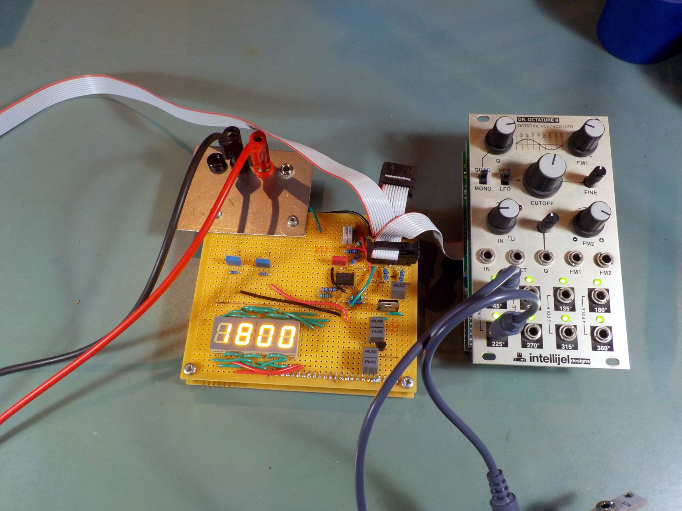
Here's a photo of it in action with an oscillating Intellijel Dr. Octature II. As advertised, the 45° and 225° outputs measure 180° apart. Note the lack of decimal point, because these displays just don't have decimal points.
Using it does require some care. I really wanted the exponential moving average feature so that I could get accurate readings (down to better than a degree of phase) even in the face of noise that makes any one single cycle's reading inaccurate. I found that it was tricky to get that to average over the right amount of time. Too slow and it takes an unreasonably long time for the reading to settle down, causing overshoot when I'm using it to adjust a Leapfrog or similar. Too fast, and the final reading still jumps around too much in response to noise.
So far I've adjusted one Leapfrog using the new meter, and it does seem to be an improvement on the oscilloscope method. But doing that also caused me to realise what was missing: I'd really like for it to have a frequency count as well, because even with the phase meter producing the required 740Hz reference signal, before I start that I need to tune the Leapfrog to oscillate at the same frequency, and at present that still requires me to get out the oscilloscope. Other adjustment tasks also require the scope anyway, so I can't dispense with it entirely, but I'd like to at least make the phase meter replace the scope for the phase-adjustment task, and it seems like adding a frequency counter feature is the way to do that. And in order to switch between modes once there's more than one mode, I think I need to add pushbuttons.
I think there's no real prospect that I could turn this into a product and sell it. As mentioned, the hardware was designed specifically around the parts I had that I wanted to use up. The microcontroller chip is probably the wrong one for this kind of device if I were going to build them commercially, and using some other chip would mean going through most of the firmware development work all over again. Even doing a plans-only DIY project like some of the others I've posted, would involve a bigger investment of time in documenting everything than I'm really willing to put in at this point. And for the number of times I will use a phase meter, it's doubtful whether even the work time I've already spent on it was wise.
However, now that I have it it will make my Leapfrog adjustments go more easily, and maybe eventually pay for itself that way. Also, it was a chance to try out some things I wanted to try, and learn some things about microcontroller programming I can hope I'll have the chance to use again in other projects.
◀ PREV Tickling twonies with triangle waves || Card payment update NEXT ▶