tag "design"
Eurorack is not a synthesizer format
Despite my having been involved in Eurorack for a number of years, there are still some important points that mystify me about the system and the community. Often I look at forum threads in which Eurorack users are looking for specific modules or features and I wonder, why would anyone want that? I recently figured out something I think sheds light on the situation: Eurorack is not actually a synthesizer format! READ MORE
Build your own commercial module part 4: manufacturing
I've written a lot about module design because from my point of view, that's the fun part. It's tempting to sit down with pen and paper, draw some schematics and sketches, maybe even build out some of those circuits on the breadboard, and then think you're close to having completed your very own commercial modules. If you have a workable design, then in one sense, you are close to being "finished." But in another important sense, it means you're just ready to start doing the real work: because with a finished design, then you still face the question of how to produce modules to that design in commercial quantities, and get people to pay you for those modules. READ MORE

Build your own commercial module part 3: firmware and documentation
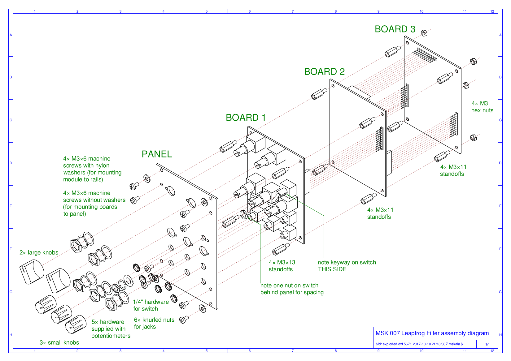
There's a lot more to a commercial module design than just the physical module that you can touch. If, as is the case with many new designs, the module includes any kind of computer, microcontroller, or other programmable device, then you need to have the program for that device. Usually, the program will be called firmware - software that becomes part of the hardware. Even a module without a conventionally programmable CPU in it may need something like an FPGA bit stream. Even a basically analog design may have some programmable aspect. For instance, my Leapfrog VCF design was originally intended to be programmable for different filter curves by substituting different resistor values on one of the three circuit boards. Creating this intangible programming information is part of creating the module, but also separable from the main task of circuit design. READ MORE
Build your own commercial module part 2: design and development
Once you have a clear idea of what commercial module you're trying to build, the design concept as described in the first part of this article series, you face the task of turning that concept into a design as such: an electronic circuit with all the details specified so that it can be manufactured on a commercial basis, with all the necessary side items like the layout of a printed circuit board, information on where to get all the parts, physical shapes of things like panels, and so on. This kind of design work is critically important to the success of the product, but it also demands a lot of technological skill, so it's often the stage where it makes sense to bring in a consultant to help. READ MORE

Build your own commercial module part 1: the design concept
There's a pretty natural progression in the modular synthesizer hobby (the addiction, if you prefer). People start out buying commercial modules; maybe they go through a few rounds of selling off modules that they find just aren't quite right; eventually, they come to the idea of wanting to build their own modules with exactly the features they want; and although doing DIY just for oneself is a viable hobby too, many hobbyists want to take the next step, of going pro and building and selling their own commercial modules. READ MORE
What's your soldering success rate?
Soldering mistakes are by far the most common thing to go wrong in do-it-yourself electronics. It seems like I spend most of my tech-support time gently urging customers with failed kit builds to re-check their soldering, and when I have problems in my own builds, those also usually turn out to be soldering-related. Everybody, myself included, tends to think of failed components as a likely cause of problems, and we spend a lot of time doing differential diagnosis to figure out which components might have failed; but then once the problem is narrowed down to a single component, the actual issue usually turns out to be a bad solder joint on that component, not the component itself. The real point of the debugging is often just to figure out which solder joints to look at more closely. READ MORE
More about DC coupling
Operational amplifiers ("op amps") are popular analog building blocks, especially in synthesizer electronics, because it's easy to analyse what they do to voltages. The first rule of op amp analysis is that (in negative feedback configurations, and when this is possible) the amplifier moves its output voltage in order to make its input voltages equal. That is useful in building circuits to manipulate DC voltages. READ MORE
Electrolytics for AC coupling
There are some special considerations relevant to electrolytic capacitors in AC coupling applications, and that's the topic of this second part of the series on AC and DC coupling. Low impedances and low cutoff frequencies require high capacitance values, and electrolytic capacitors may be the only practical way, or at least a very appealing way, to achieve those values. READ MORE
AC and DC coupling
I overheard somebody asking about the plusses and minuses of DC coupling, and AC coupling capacitors, and being told to read the detailed explanation of such things I'd written on this Web site. I was flattered to think the speaker found my article helpful, especially because I'd never actually written one about that! READ MORE
All about levels
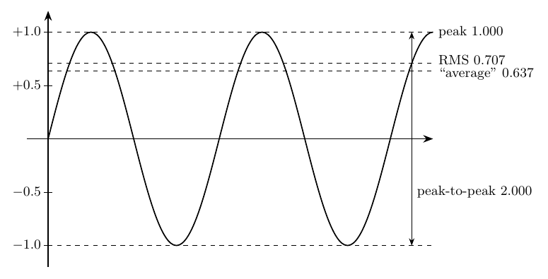
There's a lot of confusion in the modular synth world about signal levels. We often don't have a clear idea of what can plug into what, even within the modular rack; let alone when it comes to interfacing with other equipment. I've been working on guitar pedal designs recently and connections between those and modular often raise level-conversion issues. A whole lot of unnecessary "external input" and "external output" modules are sold to newbie wigglers who've been told that modular and other-equipment levels are fundamentally different and need to be converted - but although usually unnecessary in most modular racks, such modules do also serve useful purposes in certain contexts. What is really going on with signal levels? In this article I'll go through some of the concepts used for describing signal levels accurately, then talk about some of the levels commonly seen in audio work. READ MORE

Equivalent circuits
Thinking in terms of equivalent circuits is one of the basic mental skills needed for understanding electronics. I use the concept of an equivalent circuit implicitly in a lot of my writing about other things, but it's probably worth stepping back and learning about equivalent circuits in themselves. READ MORE
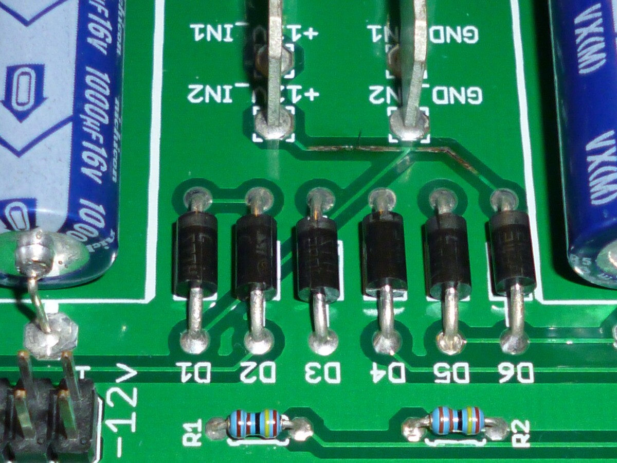
PCB design mistakes
Electronic design is sometimes imagined to begin and end with the schematic. Whoever drew the schematic gets the "designer" credit; hobbyists search the Web for "free schematics" and just assume they will encounter no issues getting from there to a working build; and technical documentation for modules (including my own) focuses on displaying and explaining a clear schematic rather than giving much or any coverage to the PCB design. READ MORE
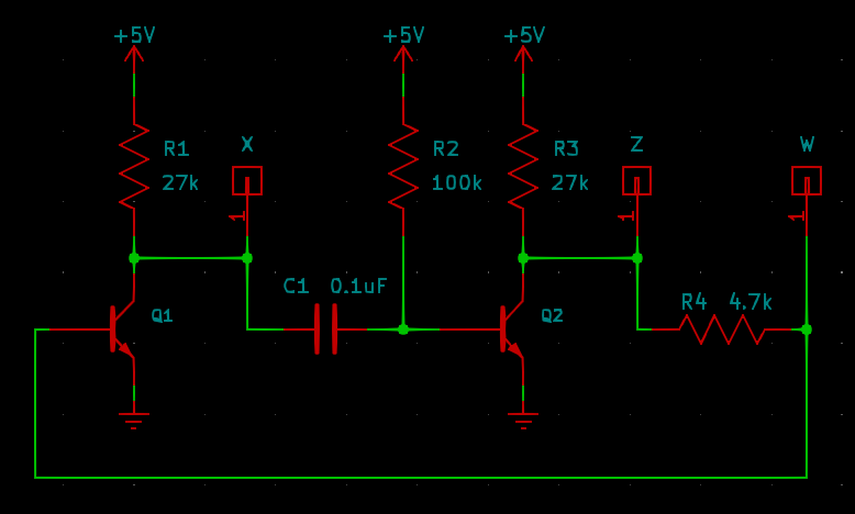
Logic, before ICs
So, you want a simple digital logic function in a synthesizer. Maybe it's an AND gate, or a couple of XORs, maybe as much as a shift register. How will you build it? READ MORE
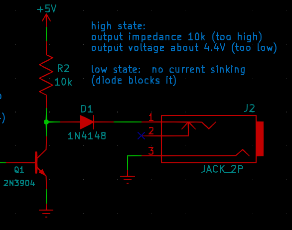
Design mistakes in synth schematics
There are a lot of bad synthesizer schematics on the Web, and it doesn't hurt their popularity. As a designer who tries to get everything right, it's somewhat disheartening to see designs with obvious, simple flaws get built commercially and cited as positive examples - and it's even worse when someone has trouble with one of my modules because they tried to connect it to the latest popular whiz-bang box which has bad levels or whatever and does not play nicely with others. In this article I'm going to talk about some of the problems I see time and time again both in free schematics published for DIY hobbyists, and in commercial modules. READ MORE
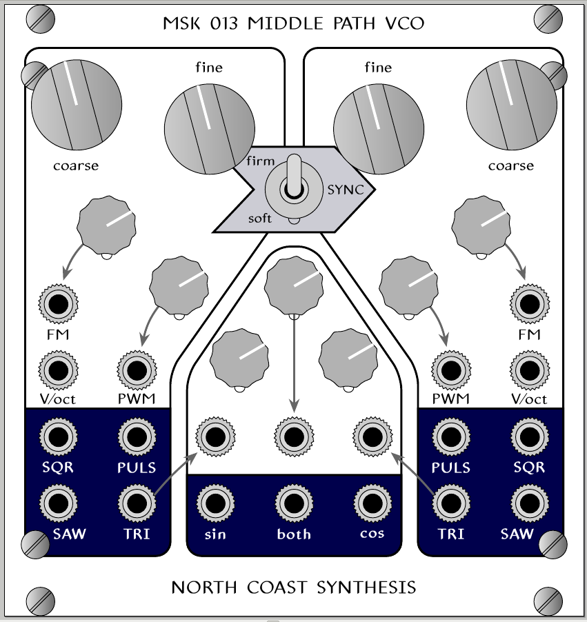
Middle Path VCO development gallery
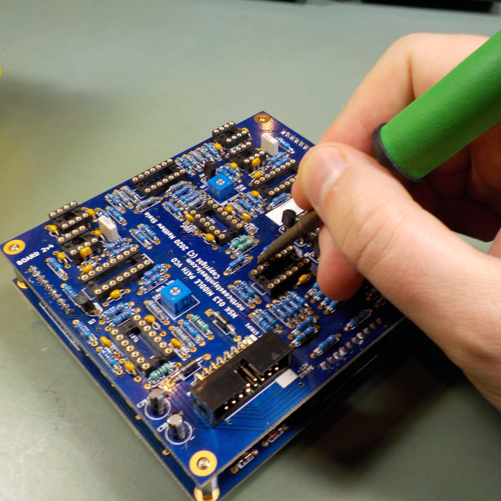
In the last several weeks I've been working on development for my next product, which I'm ready to announce will be called the MSK 013 Middle Path VCO. It's planned to be a "complex" VCO design with two independent triangle cores that can be synced, and a special waveshaping section based on the Barrie Gilbert sine shaper modified to produce quadrature output; that makes it capable of some through-zero phase modulation effects even though the cores themselves are not through-zero. I've been posting pictures from my development process in other places, and this posting gathers some of those together. READ MORE